Configuration Selection — How German Engineers Specify UL 5359
For German engineers searching UL 5359 450C Mica multi conductor wire Deutschland, the most practical question is configuration selection — how many conductors, at what AWG, with what optional features for a specific application. UL 5359’s listing permits significant configuration flexibility, but the right choice depends on application function. The decision framework below covers the most common configurations.
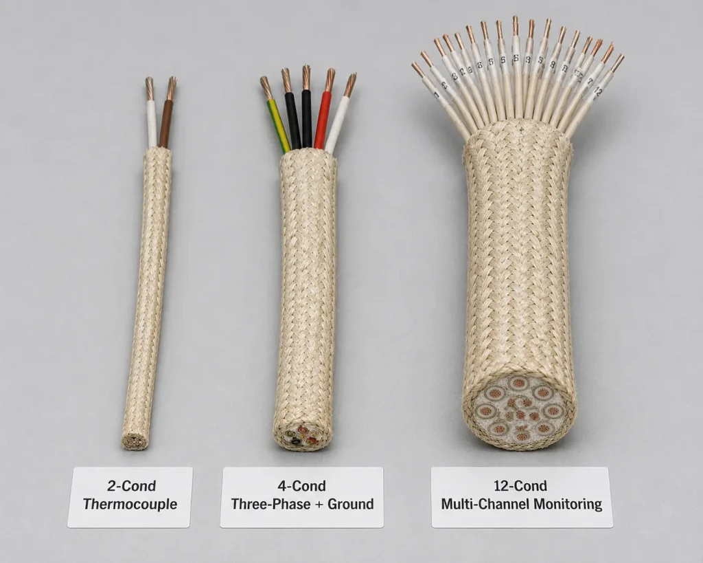
Configuration 1 — 2-Conductor for Thermocouple Measurement
Typical applications: Type K, Type N, or Type J thermocouple measurement leads in industrial furnaces, kilns, and high-temperature process equipment.
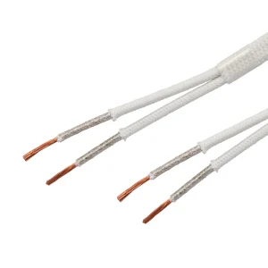
Configuration: 2 individually mica-insulated conductors (typically 20 AWG or 22 AWG), cabled together with mica glass binder. Optional treated glass braid covering for additional mechanical protection.
Why this configuration: Thermocouples generate millivolt-level signals between two specific conductor materials (chromel/alumel for Type K). The 2-conductor cable maintains the two thermocouple leads in fixed position relative to each other, preserving the measurement geometry through the cable run. The 600V isolation rating easily covers signal levels with significant margin.
Configuration 2 — 3-Conductor for 3-Wire RTD or Single-Phase + Ground
Typical applications: Pt100 or Pt1000 RTD measurements (3-wire bridge configuration) in industrial process equipment, or 120V/240V single-phase + ground power feed for small instruments mounted in high-temperature zones.
Configuration: 3 individually insulated conductors at 18-22 AWG for RTD applications, or 12-16 AWG for power applications. Cabled with mica glass binder.
Why this configuration: 3-wire RTD measurements require three conductors with consistent thermal exposure (all three at same temperature ensures balanced bridge measurement). The 3-conductor cable provides this naturally. For power applications, the 3-conductor consolidates phase, neutral, and ground in a single cable.
Configuration 3 — 3+1 Conductor for 480V Three-Phase + Ground
Typical applications: 480V three-phase power feeds in industrial heat equipment — heat treatment furnaces, glass production heating circuits, large industrial drying equipment.
Configuration: 4 individually insulated conductors (3 phases + ground) at 12-4 AWG depending on current rating. Cabled with mica glass binder and fiberglass fillers for cable shape. Treated glass braid overall covering typically specified.
Why this configuration: 480V three-phase distribution requires three phase conductors at consistent thermal exposure (to avoid uneven phase temperature derating). The dedicated ground conductor provides fault current path. Cable assembly simplifies routing through high-temperature equipment chassis.
Configuration 4 — 4-7 Conductor for Multi-Channel Instrumentation
Typical applications: 4-wire RTD measurements (highest accuracy bridge configuration), multi-channel temperature monitoring in industrial furnaces with 3-6 measurement points, instrumentation power + signal combinations.
Configuration: 4-7 individually insulated conductors at 18-22 AWG for instrumentation, or 14-20 AWG for mixed power/signal applications. Cabled with mica glass binder and fiberglass fillers.
Why this configuration: Mid-range multi-channel installations balance conductor count with cable diameter. 4-7 conductors fit comfortably in the smaller cable diameter range (10-15mm) while providing enough channels for typical instrumentation needs.
Configuration 5 — 10-30 Conductor for Heavy Multi-Channel Monitoring
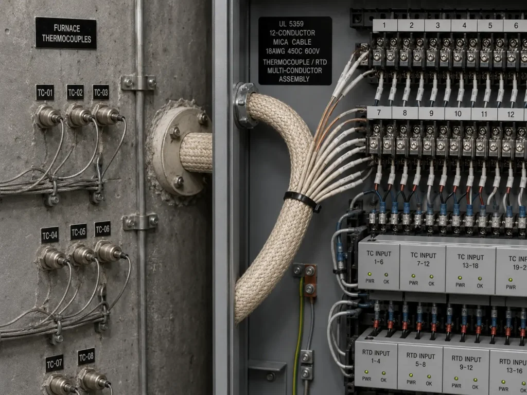
Typical applications: Large industrial heat equipment with extensive monitoring requirements — steel mill heat treatment lines with 10+ temperature zones, glass production equipment with continuous temperature profiling, large industrial furnaces with multi-point heating element monitoring.
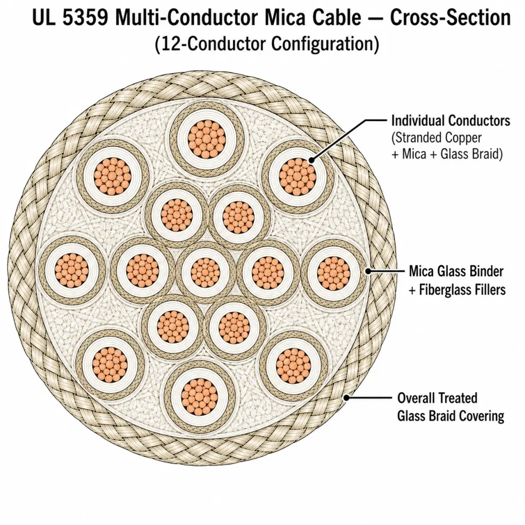
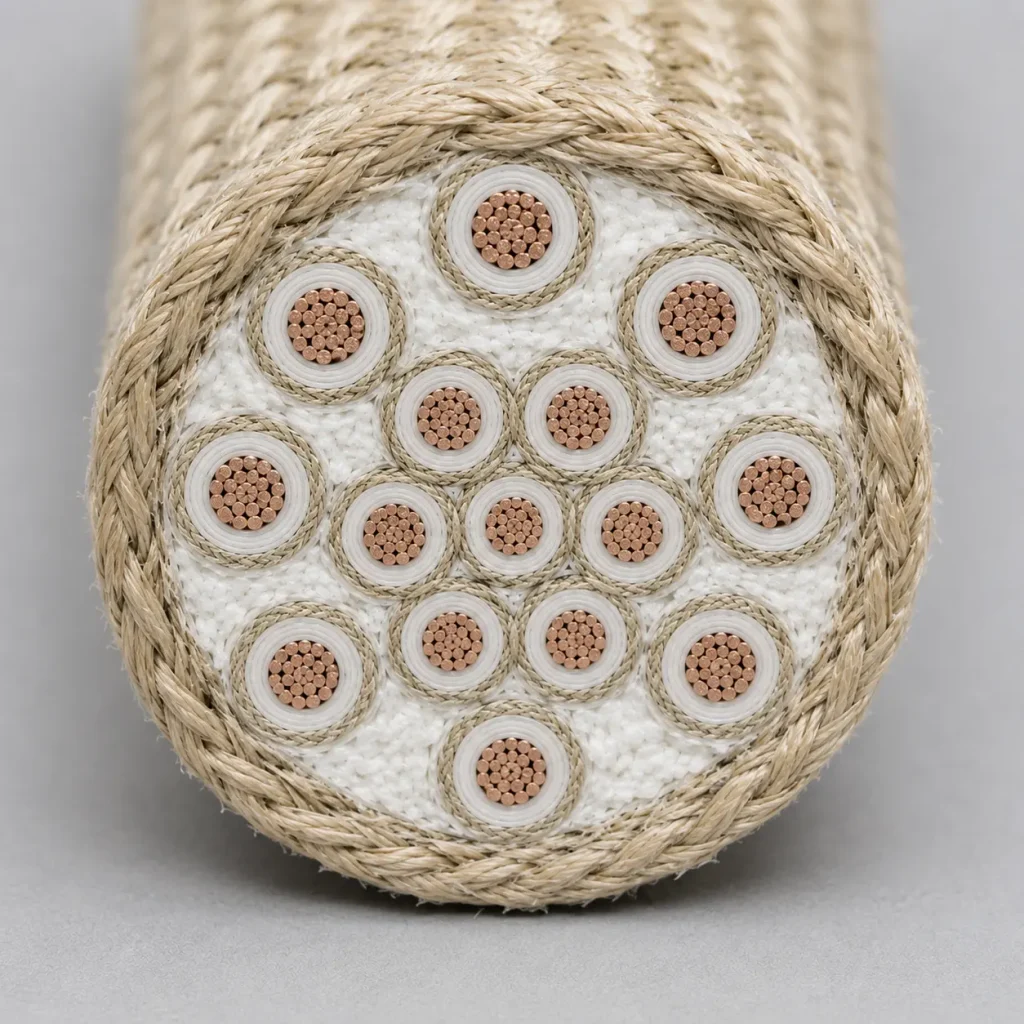
Configuration: 10-30 individually mica-insulated conductors at 18-24 AWG, cabled together with mica glass binder and fiberglass fillers. Treated glass braid overall covering essential at this conductor count for mechanical robustness.
Why this configuration: Consolidates extensive measurement and control wiring into a single cable run rather than dozens of individual conductors. The cable diameter typically reaches 20-35mm at the higher conductor counts, requiring larger spool diameters and careful routing planning.
Conductor Identification Strategies
For multi-conductor UL 5359 cables, conductor identification at the cable ends is critical for correct termination. CableApex supports three identification approaches:
Color-coded mica tape — Individual conductors use different colored mica tape during insulation, allowing visual identification at cable ends. Color palette is limited compared to polymer wires (mica pigmentation is more constrained) but typically 6-8 distinct colors are achievable.
Numbered tape labels — Individual conductors carry numerical identification (1, 2, 3, etc.) on the mica tape during production. Provides unlimited identification capability for cables with many conductors.
Position coding — For cables with a known conductor arrangement (e.g., 7-conductor hexagonal: 1 center + 6 surrounding numbered clockwise from 12 o’clock), position itself identifies the conductor. Most efficient for cables where the arrangement is documented in the equipment installation manual.
UL 5359 Specifications
| Parameter | Value (per UL Subject 758) |
|---|---|
| UL Style | AWM 5359 |
| UL File Number | E333030 (Follow-Up Service) |
| UL Designation | Multi-conductor cable assembly |
| Individual Conductor AWG Range | 30 AWG – 4/0 AWG |
| Voltage Rating | 600V AC |
| Temperature Rating | 200°C or 450°C |
| Individual Conductor Insulation | Mica with treated glass braid |
| Cable Assembly | 2+ conductors cabled together, max 1.500 inch O.D., mica glass binder + fiberglass fillers |
| Conductor Count Range | 2 to ~30 (depends on individual conductor AWG) |
| Optional Overall Covering | Treated glass braid (silicone varnish or TFE finish) |
| Conductor Identification | Color-coded, numbered, or position-coded options |
| Flame Rating | Horizontal Flame per UL Subject 758 |
| Compliance | UL Subject 758 (AWM), RoHS, REACH |
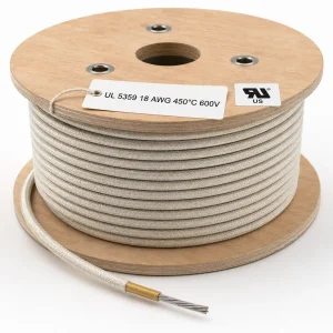
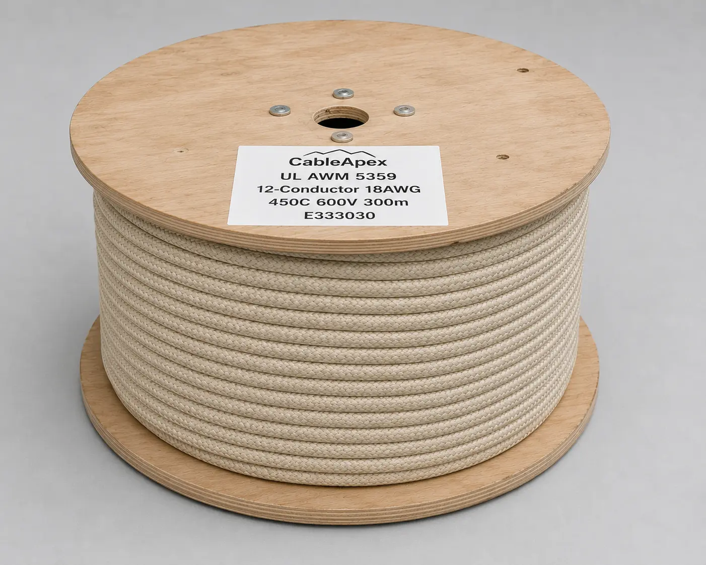
| Marking | CableApex · UL AWM 5359 · Conductor Count + AWG · 600V · 200°C/450°C · E333030 |
Engineering Notes from CableApex
- “Can I mix different AWG sizes in a single UL 5359 cable?” Yes, the UL listing permits this. A common configuration is 3 power conductors (e.g., 10 AWG) plus 4 signal conductors (e.g., 18 AWG) in a single cable assembly. The mica glass binder accommodates the different conductor sizes by filling the resulting gaps. This consolidates power + signal routing into a single cable run, useful for equipment where the same cable run serves both power and monitoring functions. Specify the AWG and quantity of each conductor type in the order.
- “What’s the typical bend radius for UL 5359 cable?” The minimum bend radius depends on cable diameter — typical recommendation is 6-8x the cable’s overall diameter for one-time installation bends, and 10-12x for installations requiring future re-routing. For a 25mm diameter cable, this means 150-200mm minimum bend radius for installation, 250-300mm for service-friendly routing. Tighter bends than these guidelines risk damaging the mica insulation through layer slip or compression.
- “How do I handle conductor termination at the cable ends?” Each conductor terminates individually with appropriate crimp connectors or terminals sized for the AWG. The mica glass binder must be carefully removed at the cable end to free individual conductors for termination — typically 100-300mm of cable end is opened up depending on the equipment’s terminal block spacing. The overall treated glass braid covering should remain intact up to where it transitions into the termination area. CableApex can supply UL 5359 cables with factory-prepared termination ends to a specific length per OEM specification.
MOQ, Packaging & Shipping
MOQ varies by conductor count, AWG, temperature class, optional covering, and production schedule. Configurations with mixed AWG sizes or many conductors (15+) typically have higher MOQ due to specialized production setup. Standard packaging: spools or reels sized appropriately for cable diameter. Export documentation: Commercial Invoice, Packing List, Certificate of Origin (CCPIT), Bill of Lading, UL Recognition reference letter (File No. E333030), RoHS Declaration, REACH SVHC Declaration, MSDS. HS Code: 8544.49. CIF Hamburg or Rotterdam, transit time 25–30 days from Shanghai or Ningbo origin port.
Related UL Mica Styles for Multi-Conductor Applications
UL 5359 buyers commonly cross-reference: UL 5476 (450°C / 600V mica + glass braid, 30-4/0 AWG — alternative multi-conductor construction), UL 5128 (450°C / 300V mica tape + glass braid with optional multi-conductor, 24-4 AWG — lower voltage alternative), UL 5360 (200°C or 450°C / 300V single-conductor mica + glass braid, 30-4/0 AWG — single conductor companion Style), and UL 5107 (200°C or 450°C / 600V mica with optional multi-conductor, 26-550 kcmil).