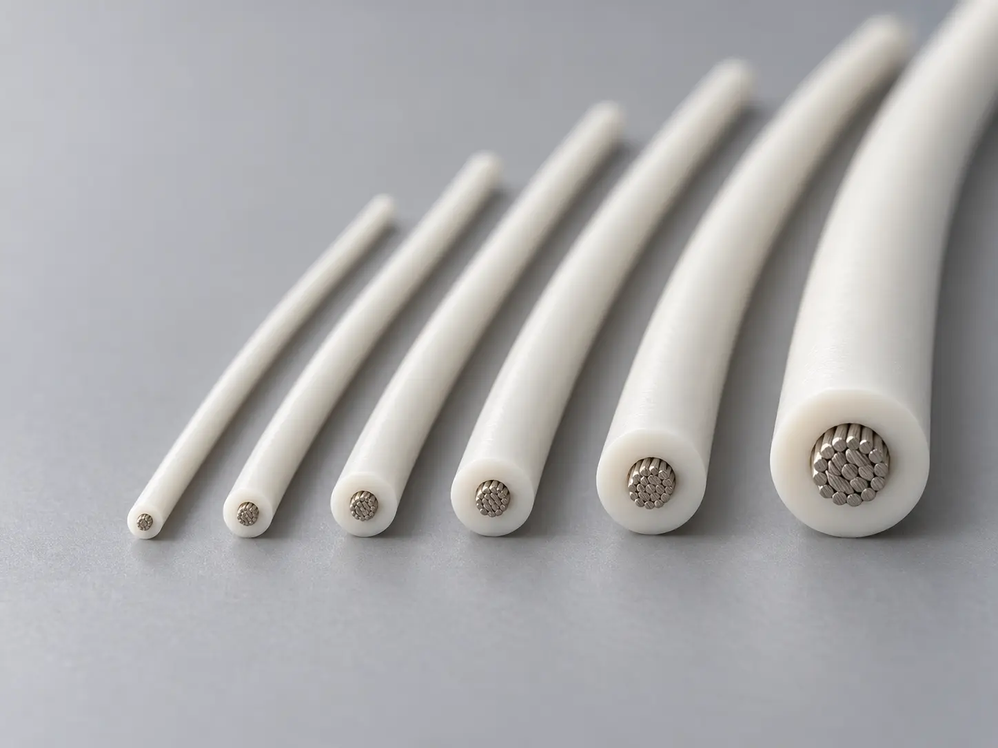
UL AWM Style 3071 — 30 Mil Silicone Rubber Construction
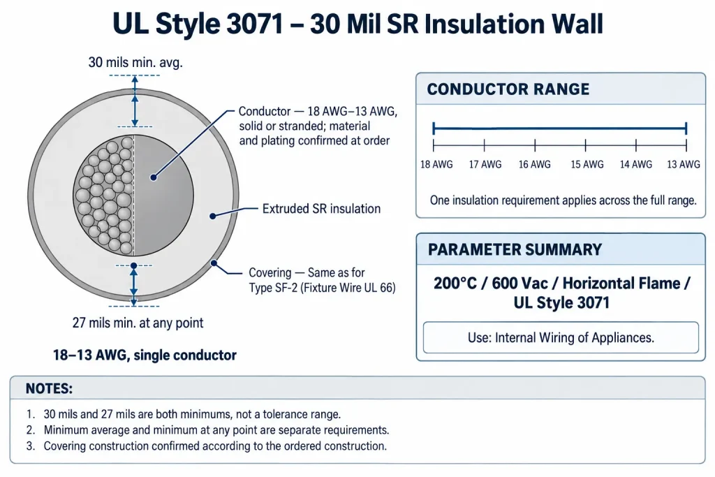
UL AWM Style 3071 is a single-conductor construction with extruded insulation, rated 200°C and 600 Vac with a Horizontal flame classification. The Style record specifies extruded SR (silicone rubber) insulation with a minimum average thickness of 30 mils and a minimum thickness at any point of 27 mils, over a conductor range of 18 AWG to 13 AWG, solid or stranded. The covering is stated as “Same as for Type SF-2 (Fixture Wire UL 66).” The Use is “Internal Wiring of Appliances.”
This page deals specifically with that insulation construction: what the two thickness requirements mean, how they apply across the full 18–13 AWG range, how the Type SF-2 covering reference should be read, and which details remain order-specific rather than Style-defined. For a general overview of the Style and the individual constructions offered under it, see the UL 3071 Silicone Wire category.
Confirmed UL 3071 Technical Specifications
| Parameter | UL AWM Style 3071 record |
|---|---|
| UL AWM Style | 3071 |
| Construction | Single Conductor with Extruded Insulation |
| Temperature rating | 200°C |
| Voltage rating | 600 Vac |
| AWG range | 18 AWG – 13 AWG |
| Conductor form | Solid or stranded |
| Insulation | Extruded SR |
| Minimum average insulation thickness | 30 mils (0.76 mm) |
| Minimum insulation thickness at any point | 27 mils (0.69 mm) |
| Covering | Same as for Type SF-2 (Fixture Wire UL 66) |
| Flame | Horizontal flame |
| Marking | General |
| Use | Internal Wiring of Appliances |
Four points in this table need clarification. First, the millimetre values are direct unit conversions of the mil values (1 mil = 0.0254 mm); they are not separate design dimensions. Second, the voltage rating is stated as 600 Vac only; the record contains no DC rating, and none should be assumed. Third, the conductor entry defines size range and form only; conductor material, plating and strand construction are not specified by the Style and are confirmed according to the ordered construction. Fourth, the covering and marking entries are reproduced exactly as written in the record; how each is handled for a specific order is explained in the sections below.
30 Mil Minimum Average and 27 Mil Minimum Point Thickness
Style 3071 sets two separate insulation thickness requirements, and a qualified construction must meet both of them.
- Minimum average thickness — 30 mils (0.76 mm): the average of wall-thickness measurements taken around the insulation cross-section must not fall below 30 mils.
- Minimum thickness at any point — 27 mils (0.69 mm): the thinnest point anywhere in the insulation wall must not fall below 27 mils.
The two requirements are independent. A wall whose average exceeds 30 mils still fails if a single thin spot measures below 27 mils. A wall with no point below 27 mils still fails if its average is below 30 mils. The 3-mil difference between the figures is therefore not a tolerance band around a nominal value, and it is not a range within which the wall is expected to sit. Both figures are floors.
Neither figure is a nominal, exact or target wall thickness. The actual extruded wall of a given construction may exceed 30 mils; its value belongs to the ordered construction, not to the Style. For the same reason, the finished outside diameter cannot be derived by adding twice 30 mils to a conductor diameter. Where an appliance design constrains the finished diameter — for grommets, clamps, terminal housings or internal routing channels — that dimension belongs in the drawing and should be confirmed against the ordered construction.
The record gives a single insulation requirement for the whole Style. The 30-mil minimum average and 27-mil minimum at any point apply equally to every conductor size from 18 AWG to 13 AWG; there is no gauge-dependent thickness table for Style 3071.
18–13 AWG Solid or Stranded Conductor Range
The conductor field reads “18 AWG – 13 AWG, solid or stranded.” This covers 18, 17, 16, 15, 14 and 13 AWG, each in solid or stranded form. The Style does not designate any one size as standard; every size in the range carries the same rating, insulation and covering requirements.
The conductor field does not define conductor material, plating, number of strands, strand diameter, lay length or conductor resistance. The Style also assigns no current rating to any size. Current-carrying capacity inside an appliance is determined by the end product’s design and its own evaluation; it is not derived from the AWM Style or from AWG alone, and no ampacity figure is given here.
If an appliance drawing calls for a particular conductor material, plating or stranding, that is an order-specific requirement. It should be stated in the RFQ and confirmed for the qualified construction. Sizes outside 18–13 AWG fall outside Style 3071.
Type SF-2 Covering Reference
The covering field of Style 3071 reads: “Same as for Type SF-2 (Fixture Wire UL 66).” The Style record does not describe the covering material in its own words; it refers to the covering provisions for Type SF-2 fixture wire in UL 66.
That reference is kept here in its original form. It is not restated as a specific braid or sleeve material, and no mechanical, abrasion or thermal properties are attributed to it, because the Style 3071 record does not state any. If a drawing requires a particular covering material, construction or appearance, that requirement should be written into the RFQ and confirmed against the ordered construction, including its relationship to the Type SF-2 reference.
200°C / 600 Vac Rating and Horizontal Flame
The rating field reads “200 deg C, 600 Vac, Horizontal flame.” 200°C is the maximum rated temperature of the Style, and 600 Vac is its rated voltage. Neither value implies a service life, a thermal-ageing period or a margin above the rating, and neither translates into a current, wattage or load figure.
Horizontal flame is the flame classification in the record. It is not VW-1, FT1 or FT2, and no vertical flame rating forms part of the Style. If an end-product specification calls for a different flame test, that is a separate requirement to be confirmed for a specific construction; it cannot be assumed from Style 3071.
These ratings apply to the wire as a component. They do not certify the appliance in which it is installed; the appliance’s own evaluation determines whether the component is acceptable in that design.
Internal Wiring of Appliances
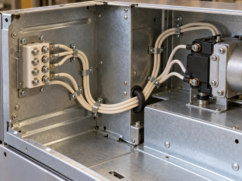
The Use field is “Internal Wiring of Appliances.” Style 3071 is intended for wiring inside an appliance: connections between internal components within the appliance enclosure, where the appliance design specifies Style 3071 and the 200°C / 600 Vac rating and construction are appropriate.
The Use does not extend beyond the appliance. Style 3071 is not building wire, field wiring, branch-circuit wiring or conduit wiring, and it is not an appliance supply cord, extension cord or portable cord. Neither the rating nor the conductor range adds uses: a 600 Vac rating does not make it a power-distribution cable, and a 200°C rating does not identify any particular appliance type.
What Style 3071 Does and Does Not Define
The Style record defines the construction (single conductor, extruded insulation); the rating (200°C, 600 Vac, Horizontal flame); the conductor range and form (18–13 AWG, solid or stranded); the insulation material and its two minimum thicknesses (extruded SR, 30 mils minimum average, 27 mils minimum at any point); the covering reference (Same as for Type SF-2, Fixture Wire UL 66); the marking field (General); and the Use (Internal Wiring of Appliances).
The Style record does not define:
- conductor material, plating or strand construction
- conductor resistance or current rating
- nominal insulation wall, finished outside diameter or diameter tolerance
- a DC voltage rating
- a vertical flame rating
- bend radius, flex performance or service life
- colours, put-up lengths or packaging
Common Procurement Errors
- Treating 30 mils as the nominal wall and calculating a finished diameter from it.
- Reading 30 mils and 27 mils as the upper and lower limits of a tolerance range.
- Assuming a specific covering material from the Type SF-2 reference without confirming the ordered construction.
- Assuming bare or tinned copper is part of the Style definition.
- Assigning a current rating to a conductor size on the basis of AWG alone.
- Assuming a VW-1, FT1 or other vertical flame rating.
- Adding a DC rating or writing the voltage as a combined AC/DC value.
- Specifying Style 3071 for wiring outside the appliance enclosure.
- Ordering a size outside 18–13 AWG under Style 3071.
How to Specify UL 3071 30 Mil Silicone Wire in an RFQ
An RFQ should keep the Style-fixed parameters apart from the order-specific details. The Style fixes the construction, 200°C, 600 Vac, Horizontal flame, extruded SR, the 30-mil minimum average and 27-mil minimum-point thicknesses, the Type SF-2 covering reference and the Use. The following must be stated by the buyer and confirmed for the ordered construction:
- required AWG within 18–13 AWG
- solid or stranded conductor
- conductor material or plating, if specified by the drawing
- colour
- exact covering requirement, and whether the drawing refers to the Type SF-2 covering reference
- finished outside diameter or other dimensional constraint, if applicable
- marking requirement
- quantity
- packaging requirement
- documentation requirement
- the appliance internal-wiring application in which the wire will be used
Where a drawing contains a requirement that Style 3071 does not define, such as a resistance limit, a dimensional tolerance or an additional flame test, identify it explicitly so it can be confirmed before quotation rather than assumed.
UL Marking and Documentation
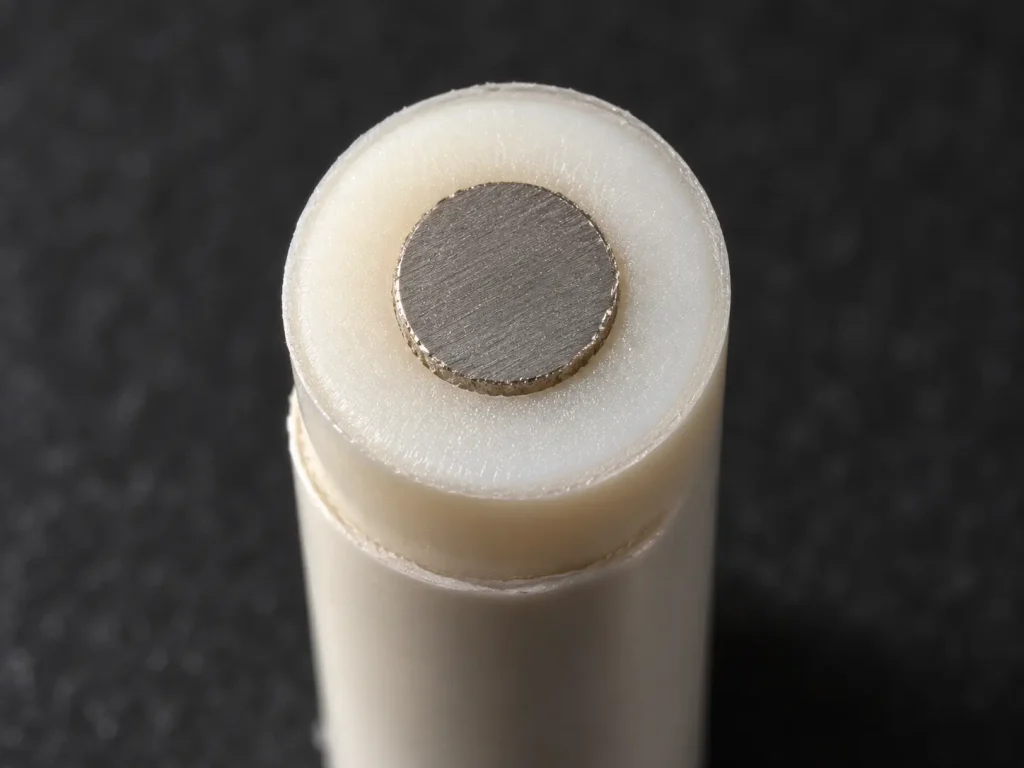
Style 3071 wire is supplied as UL-recognized component wire where supplied under qualified manufacturing scope. The marking field of the Style record reads “General”; it does not prescribe a fixed print legend. UL marking is applied according to the confirmed ordered construction, and marking content and format should be confirmed at the order stage.
Applicable RoHS / REACH documentation can be confirmed according to the ordered construction. CE, UKCA, CSA, FT1, VW-1, CPR, VDE, DIN, EN and IEC are not declared for this product.
Commercial, origin, compliance and transport documents are identified during quotation and confirmed according to the order.