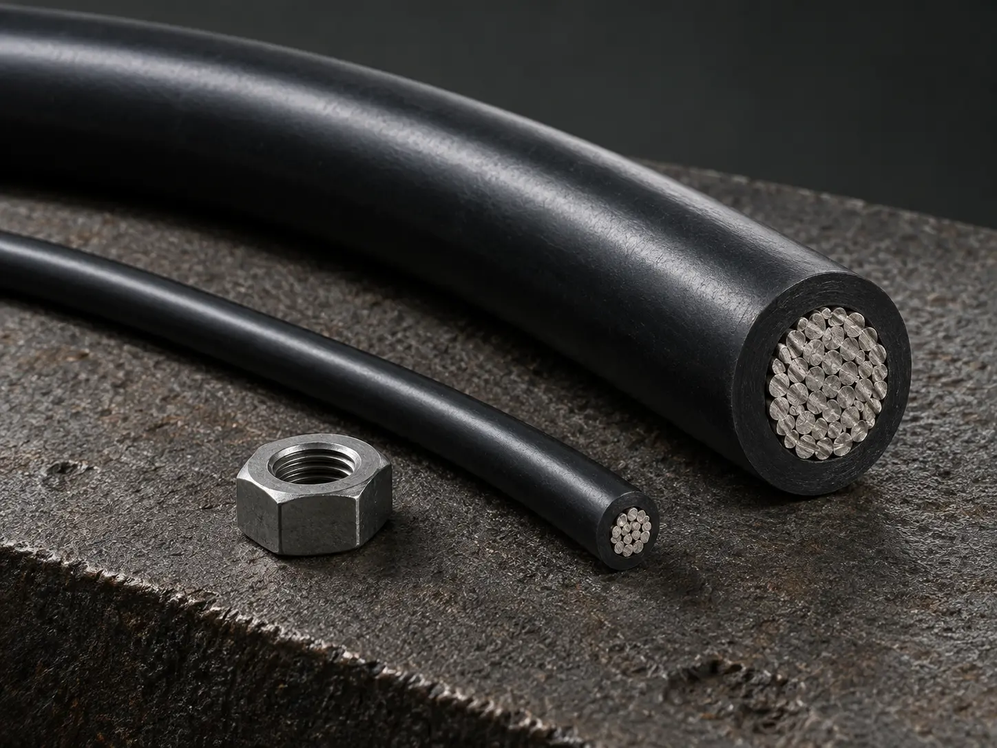
UL 3271 125°C XLPE Motor Lead Wire Across the Full Conductor Range
This page covers UL AWM Style 3271 as a construction type: a single conductor with extruded XLPE insulation, rated 125°C with 600 Vac and 750 Vdc voltage ratings and a Horizontal Flame designation. It is written for motor, appliance and equipment OEM engineering and procurement teams working from a drawing, BOM or wire specification.
Two characteristics define how this Style is specified. Its conductor range is unusually wide, running from 30 AWG to 2000 kcmil with six different insulation wall groups along the way. And its official Use names motor leads explicitly: “For use as Motor Leads or Internal Wiring of appliances.”
A third element is optional and frequently misread: the record permits an extruded or non-extruded semi-conductive polymeric layer over the conductor, supplied only when specified. Each of these is set out below, together with what the Style leaves to the ordered construction.
Confirmed UL Style 3271 Construction and Ratings
| Parameter | Requirement |
|---|---|
| UL AWM Style | 3271 |
| Product Description | Single conductor with extruded insulation |
| Temperature Rating | 125°C |
| AC Voltage Rating | 600 Vac |
| DC Voltage Rating | 750 Vdc |
| Flame | Horizontal Flame |
| Style Conductor Range | 30 AWG–2000 kcmil |
| Conductor Form | Solid or stranded |
| Optional Semi-Conductive Layer | Optional; an extruded or non-extruded semi-conductive polymeric layer may be provided over the conductor |
| Insulation | Extruded XLPE |
| Marking | General |
| Official Use | For use as Motor Leads or Internal Wiring of appliances. |
| Optional Tag | 2500 volt peak – For Electronic Use Only |
| Documentation | UL marking and compliance documents according to the confirmed ordered construction |
| RoHS / REACH | Applicable RoHS / REACH documentation can be confirmed according to the ordered construction |
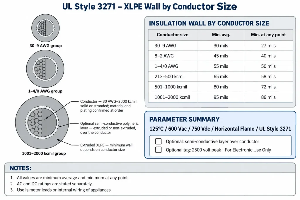
| Conductor size | Minimum average thickness | Minimum thickness at any point |
|---|---|---|
| 30–9 AWG | 30 mils | 27 mils |
| 8–2 AWG | 45 mils | 40 mils |
| 1–4/0 AWG | 55 mils | 50 mils |
| 213–500 kcmil | 65 mils | 58 mils |
| 501–1000 kcmil | 80 mils | 72 mils |
| 1001–2000 kcmil | 95 mils | 86 mils |
Ten points to clarify about the tables above:
- The temperature rating is 125°C, stated without a duty qualifier.
- The AC and DC ratings are listed separately as the record states them. They are not combined into an AC/DC rating or written as 600/750 V.
- 750 Vdc is a rating for the wire, not an equipment or drive system rating.
- 2500 volt peak – For Electronic Use Only is an optional tag indication, not a normal working-voltage rating.
- The semi-conductive polymeric layer is optional and may be extruded or non-extruded, supplied only where specified and confirmed.
- The insulation wall requirement depends on the conductor size group, and values from one group do not apply to another.
- Each group gives a minimum average thickness and a minimum thickness at any point: two independent minimums, not nominal or exact wall values.
- Conductor material, plating, strand count, strand diameter and lay length are not defined by the Style.
- Finished OD, OD tolerance, conductor resistance, metric cross-section and ampacity are not defined by the Style.
- 30 AWG–2000 kcmil is the Style scope, not a stock list, and availability of a given size and configuration is confirmed per enquiry.
One Style Across Six Wall Groups
The conductor range spans from fine internal leads to conductors of several hundred kcmil, and the insulation requirement rises in six steps to match: 30 mils minimum average and 27 mils minimum at any point at 30–9 AWG, through 45/40, 55/50, 65/58 and 80/72 mils, up to 95 mils minimum average and 86 mils minimum at any point at 1001–2000 kcmil.
Two consequences follow for a specification. A single wall figure quoted for “UL 3271” is wrong for every group it did not come from, and the group that governs is the one containing the ordered size. Within each group both values apply together: the average wall must meet the first figure, and no point of the wall may fall below the second.
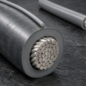
Minimum wall values also do not produce a finished outer diameter. Actual OD depends on the conductor material and form, the actual conductor dimensions, the applicable insulation group, whether the optional semi-conductive layer is applied, the XLPE extrusion and manufacturing tolerance. Where motor slot entry, lead-out clearance, gland fit or terminal entry is controlled, state a maximum finished OD and OD tolerance in the RFQ rather than calculating one from the table.
The insulation material is extruded XLPE, also written as cross-linked polyethylene. This page does not restate it as PVC, silicone or a fluoropolymer, and does not attribute chemical, oil or solvent resistance to it, since the record contains no such rating.
The Optional Semi-Conductive Polymeric Layer
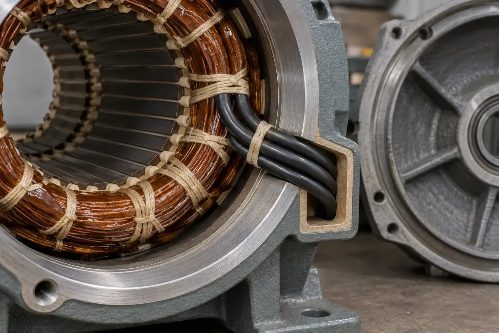
The record permits an extruded or non-extruded semi-conductive polymeric layer over the conductor. Three points matter when specifying it.
It is optional. A Style 3271 construction does not include the layer unless the buyer specifies it, so an enquiry requiring it must say so and an enquiry that is silent will be quoted without it.
Both forms are permitted, extruded or non-extruded. Where a drawing controls which, that requirement should be stated so the qualified construction can be confirmed.
The record assigns it no performance function. This page therefore does not describe the layer as providing stress control, corona or partial-discharge resistance, improved dielectric behaviour, inverter-duty capability or any other electrical or mechanical property. If a design relies on a defined function, that belongs in the drawing and is reviewed against the proposed construction.
Reading the 125°C, 600 Vac and 750 Vdc Ratings
The temperature rating is 125°C. This page does not describe it as continuous or continuous-duty, does not claim any higher figure, and derives no service life, thermal cycling count, motor insulation class or thermal margin from it.
The record lists 600 Vac and 750 Vdc, and both are wire ratings. Writing them as 600 V AC/DC, 600/750 Vac or 750 Vac misstates the record, and the DC figure is not presented as a drive bus rating, a system voltage or an inverter output rating.
Tags may indicate “2500 volt peak – For Electronic Use Only”, and both qualifiers stay attached whenever that tag is cited: it is a peak indication for electronic use rather than a working voltage, and no pulse, impulse or partial-discharge performance is derived from it. The flame designation is Horizontal Flame; VW-1, FT1 and vertical flame designations are not part of this record.
Conductor Construction
The Style states the conductor range and the words solid or stranded, and nothing further. The following are RFQ fields rather than Style values:
- solid or stranded form
- conductor material
- plating or surface finish
- strand count, strand diameter and lay construction, where controlled
- maximum conductor resistance, where controlled
- metric cross-section, where a drawing specifies mm² rather than AWG or kcmil
No stranding class, flexibility grade or flex life is applied here. Conductor size also assigns no circuit function or current capacity: the record gives no ampacity, and none is inferred from conductor size, the 125°C rating or either voltage figure. Motor current, duty and winding connection requirements are determined by the motor design and the applicable approval process.
Official Use: Motor Leads or Internal Wiring of Appliances
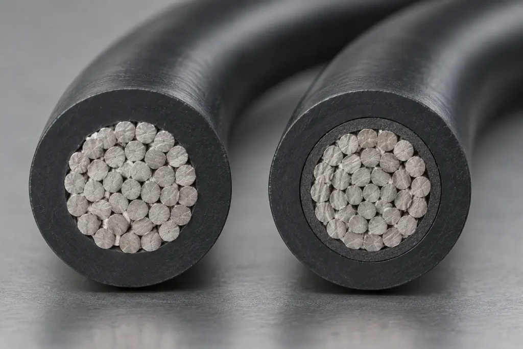
The official Use is “For use as Motor Leads or Internal Wiring of appliances.” Both categories belong to the Style, and dropping either one narrows it incorrectly.
Motor lead service is therefore within the Use as written, which is unusual among AWM Styles and is the main reason drawings specify Style 3271. That does not make the Style a motor design specification: it establishes no winding temperature class, no inverter-duty or variable frequency drive rating, no partial-discharge performance, no repeated-flexing capability and no suitability for a particular motor type or system voltage.
The Use is also not extended to building or mains installation wiring, field wiring, conduit or tray installations, external motor supply cable between equipment, portable cord, VFD output cable between drive and motor, or general power distribution. Compliance of a finished motor, appliance or assembly is established at the equipment level and is not conferred by the Style designation of one wire.
How to Specify UL 3271
A Style designation is a construction requirement, not a complete purchase specification. A complete enquiry adds:
- the UL AWM Style 3271 requirement
- the AWG or kcmil size
- solid or stranded construction
- conductor material and plating, where controlled by the drawing
- strand construction and maximum conductor resistance, where controlled
- whether the optional semi-conductive layer is required, and whether extruded or non-extruded
- insulation colour and any identification requirement
- the marking requirement
- maximum OD and OD tolerance, where controlled
- the motor lead or appliance internal wiring location
- the drawing, BOM or equipment specification
- documentation requirements, quantity and packaging or reel preference
- the destination and the requested Incoterm
No price, currency, pricing formula or price validity period is published on this page. A quotation is prepared against a defined construction and commercial scope and issued as a separate quotation document.
What Style 3271 Does and Does Not Define
Style 3271 defines:
- 125°C temperature rating
- 600 Vac and 750 Vdc voltage ratings
- Horizontal Flame
- conductor range 30 AWG–2000 kcmil, solid or stranded
- an optional extruded or non-extruded semi-conductive polymeric layer over the conductor
- extruded XLPE insulation with size-dependent minimum wall requirements across six groups
- Marking: General
- Use: For use as Motor Leads or Internal Wiring of appliances.
- optional tag: 2500 volt peak – For Electronic Use Only
Style 3271 does not universally define:
- conductor material, plating, strand count, strand diameter or lay length
- a function or performance for the semi-conductive layer
- finished OD, OD tolerance, bend radius, flex cycles or flex class
- conductor resistance, ampacity, current rating or metric cross-section
- motor insulation class, inverter duty, VFD rating or partial-discharge performance
- oil, chemical or solvent resistance
- equipment or drive system voltage ratings
- installation, field wiring or external cable suitability
- colour, reel length, MOQ, stock, lead time, production capacity or shipping term
Common Procurement Errors
- Writing “125°C continuous”, or claiming a higher temperature rating.
- Writing “600V AC/DC”, “600/750 V”, or converting 750 Vdc into an AC value.
- Presenting 750 Vdc as a drive bus or system voltage rating.
- Using 2500 volt peak as a working voltage, or dropping “For Electronic Use Only”.
- Treating the optional semi-conductive layer as standard, or assigning it stress-control, corona or inverter-duty performance.
- Quoting one insulation wall figure across the whole 30 AWG–2000 kcmil range.
- Applying one group’s wall values to a size in another group.
- Omitting the minimum-at-any-point value, or treating the minimum average as a nominal wall.
- Deriving a finished OD from the minimum wall values.
- Assuming the conductor is tinned copper, or claiming a stranding class or flexibility grade.
- Deriving ampacity from conductor size or the ratings.
- Treating the Style as a motor insulation class or an inverter-duty qualification.
- Extending the Use into VFD output cable, external motor supply cable or installation wiring.
- Describing the insulation as PVC, silicone or a fluoropolymer, or claiming oil and chemical resistance.
RFQ Information to Confirm
Style and ratings
- UL AWM Style 3271 requirement
- 125°C temperature rating requirement
- Required voltage requirement within the 600 Vac and 750 Vdc ratings
- AWG or kcmil size
Conductor and construction
- Solid or stranded construction
- Conductor material and plating requirement, if controlled by the drawing
- Strand construction, if controlled
- Maximum conductor resistance or controlled mm² cross-section, if applicable
- Whether the optional semi-conductive layer is required, extruded or non-extruded
- Maximum OD and OD tolerance, if controlled
Identification and application references
- Insulation colour and identification requirement
- Marking requirement
- Motor lead or appliance internal wiring location
- The circuit requirement for engineering review, rather than a self-derived ampacity
- Drawing, BOM or equipment specification
Commercial
- Quantity and packaging or reel preference
- Destination and requested Incoterm
- Requested UL marking and compliance documents, including any RoHS / REACH documentation requirement
UL Marking and Documentation
CableApex is an international sales and export company and does not hold a UL File for Style 3271. Supplied wire is UL-recognized component wire where supplied under a qualified manufacturing scope, with UL marking according to the confirmed ordered construction. The Style record lists Marking as General.
Applicable RoHS / REACH documentation can be confirmed according to the ordered construction. CSA, FT1, VW-1, CE and dual UL/CSA designations are not claimed here.
Commercial, origin, compliance and transport documents are identified during quotation and confirmed according to the order. They are not supplied as a fixed package with every shipment.