UL 3239 20 kVDC Power Supply Wire Overview
This page describes a specific UL AWM Style 3239 construction: a nominal 17 AWG / 1 mm² conductor, 32 × 0.20 mm stranded, silicone insulated, rated 200°C and 20 kVDC, with a finished outside diameter of 5.3 ±0.1 mm. It is built for buyers with a defined internal high-voltage DC section inside a power supply assembly, where an ordinary internal wire is not a practical match for the electrical condition and a dedicated construction needs to be confirmed against dimensional and electrical BOM requirements before quotation.
The procurement scenario is specific: an OEM engineer or sourcing team has an internal high-voltage DC section in a power supply requiring approximately 1 mm² conductor size, 200°C temperature capability, and a 20 kVDC construction. Before approving the wire, the buyer needs to verify the 32 × 0.20 mm conductor, the silicone wall thickness, the 5.3 ±0.1 mm finished OD, routing space, terminations, and end-product acceptability.
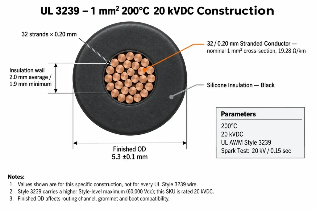
Specific 1 mm² / 20 kV Construction
| Parameter | Specific Construction |
|---|---|
| UL AWM Style | 3239 |
| Procurement size | Nominal 17 AWG / 1 mm² |
| Source-defined cross-section | 1 mm² |
| Conductor construction | 32 / 0.20 mm |
| Individual strand diameter | 0.20 ± 0.004 mm |
| Number of strands | 32 |
| Conductor resistance | 19.28 Ω/km |
| Rated temperature | 200°C |
| Rated voltage | 20 kVDC |
| Insulation | Silicone |
| Average insulation thickness | 2.0 mm |
| Minimum insulation thickness | 1.9 mm |
| Finished OD | 5.3 ± 0.1 mm |
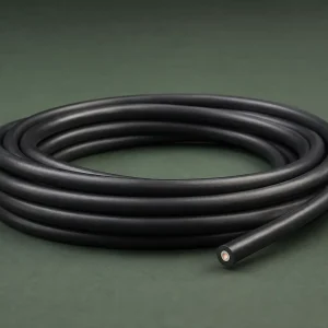
| Insulation colour | Black |
| Spark test | 20 kV / 0.15 sec |
UL AWM Style 3239 permits multiple constructions up to the Style-level maximum. This table describes this specific 1 mm², 200°C, 20 kVDC silicone-insulated construction and its associated dimensions — it is not a statement that every UL 3239 wire shares these values.
17 AWG / 1 mm²: Which Value Controls the RFQ?
The supplier construction is specified directly as 1 mm² with a 32 × 0.20 mm stranded conductor. CableApex uses 17 AWG / 1 mm² as the procurement-facing size designation; dimensional and conductor-construction approval should be based on the confirmed 1 mm², 32 × 0.20 mm specification rather than AWG terminology alone. For engineering approval, compare conductor construction, the actual cross-section requirement, conductor diameter if your drawing specifies one, and electrical resistance requirement — not the AWG label in isolation. This page does not claim a perfect mathematical identity between 17 AWG and 1 mm².
32 × 0.20 mm Conductor Construction
Strand construction is part of what differentiates this SKU from other UL 3239 constructions. The conductor contains 32 strands of 0.20 mm nominal diameter, with an individual-strand diameter tolerance of 0.20 ±0.004 mm. This page does not infer a high-flex rating, continuous-flex capability, cable-chain performance, minimum bend radius, or torsional life from strand count alone — none of these are established by the confirmed construction data.
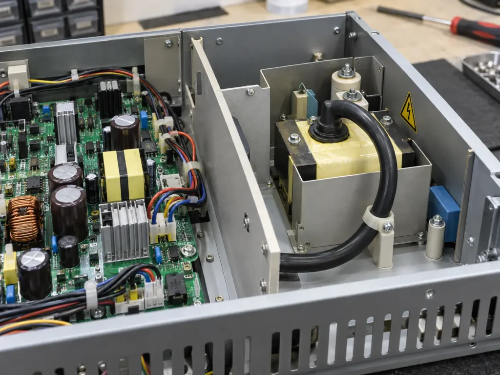
Understanding the 20 kVDC Rating
20 kVDC is the central voltage identity of this construction. This page does not describe it as 20 kVac, 20 kV AC/DC, 60 kV, or 60 kV capable, and does not mathematically convert the DC rating into an AC rating. UL Style 3239 carries a Style-level maximum of 60,000 Vdc, which is why different qualified Style 3239 constructions can carry substantially different voltage ratings — but that Style ceiling is not the rating of this SKU. This page’s UL 3239 High Voltage Wire with Optional Shield resource and our compact-module UL 3239 SKU each represent their own distinct constructions; this page’s identity remains 20 kVDC throughout.
Why a Power Supply May Need a Dedicated High-Voltage Internal Lead
A power supply assembly can contain different internal wiring zones with materially different requirements. Ordinary low-voltage internal wiring and a specific high-voltage DC section should not automatically use the same wire specification. The relevant product-selection fields for the high-voltage section include required voltage, required temperature, routing envelope, terminal interface, conductor size, and finished OD. This page does not claim that UL 3239 is automatically approved for every power supply — suitability depends on the specific equipment design and applicable acceptability determination.
200°C Wire Rating vs Power-Supply Thermal Design
This specific construction is rated 200°C. That figure describes the wire itself — it does not mean the power supply operates at 200°C, that PCB components are rated 200°C, that terminals are rated 200°C, or that the enclosure ambient may automatically be assumed at 200°C. The wire’s rating and the complete equipment thermal design are separate engineering questions that should be evaluated independently.
Silicone Insulation Wall
The confirmed silicone insulation wall for this construction is 2.0 mm average thickness and 1.9 mm minimum thickness at any point. This page does not derive a dielectric-strength relationship from wall thickness and does not state that 2.0 mm automatically provides any specified voltage margin beyond the documented construction. These are controlled dimensional parameters of this 20 kV construction, stated as confirmed values.
Finished OD: 5.3 ±0.1 mm
Finished OD is a major procurement consideration for internal power-supply layouts, since it may affect routing channels, grommets, insulating sleeves, cable clamps, high-voltage boots, terminal enclosure openings, and clearance from adjacent components. These are mechanical-interface examples a buyer checks against their own drawing — this page does not claim universal compatibility with any specific connector, grommet, or boot. If your assembly controls a maximum wire envelope, that dimension should be stated in the drawing and confirmed against the ordered construction.
20 kV Rating Does Not Determine Equipment Creepage or Clearance
The wire’s 20 kVDC voltage rating does not establish PCB creepage, air clearance, terminal spacing, connector creepage, or enclosure insulation distances. Those are equipment-level design requirements governed by the applicable end-product standard, not properties of the wire construction. This page does not publish generic spacing values, since no specific applicable equipment standard has been supplied for this construction.
Conductor Resistance
The confirmed conductor resistance for this construction is 19.28 Ω/km. This page uses this figure only as a product-specific conductor parameter and does not derive ampacity, current rating, wattage, or allowable power from it. If your project controls conductor resistance, include that requirement in your approval specification.
Spark Test Is Not the Continuous Operating Voltage
The construction data includes a spark test of 20 kV / 0.15 sec. This is a manufacturing or production test parameter — it is not presented here as an additional operating voltage rating. Manufacturing/test voltage information and continuous product rating are different parameters; the operating product rating for this construction remains 20 kVDC.
Official UL 3239 Use Boundary
UL Style 3239’s official Use is: internal wiring of TV receivers or where the acceptability has been determined by Underwriters Laboratories. Power supply internal wiring is the buyer application context for this specific product page — it is not the official UL-approved Use wording, and this page does not rewrite power supplies as a separate UL-defined use category.
Not a General Power Cable
This is an AWM internal-wiring product construction. It is not presented on this page as building wire, branch circuit cable, utility cable, medium-voltage power cable, tray cable, conduit cable, portable cord, or external equipment interconnect.
What This SKU Does Not Automatically Define
The supplied technical data does not automatically establish: ampacity, allowable circuit current, power rating, bend radius, flex-cycle rating, terminal compatibility, connector compatibility, creepage distance, clearance distance, shield, jacket, external mechanical protection, reel length, MOQ, stock availability, or production lead time. These should be confirmed according to the project where required.
Common Power-Supply RFQ Mismatches
Several mismatches recur when this construction is sourced without complete data. A buyer requests UL 3239 but omits the required voltage. A supplier quotes 15 kV when the BOM requires 20 kVDC. The nominal conductor size is similar but the strand construction differs. The 5.3 mm OD does not fit the existing routing envelope. A buyer assumes every Style 3239 product is rated 60 kV, or assumes all UL 3239 wire is silicone insulated. A buyer specifies AWG only, while the approved drawing actually controls a metric cross-section. The terminal or boot was designed for a different wire OD. Stating the exact construction — 1 mm², 32 × 0.20 mm, 200°C, 20 kVDC, 5.3 ±0.1 mm — in the RFQ removes this ambiguity.
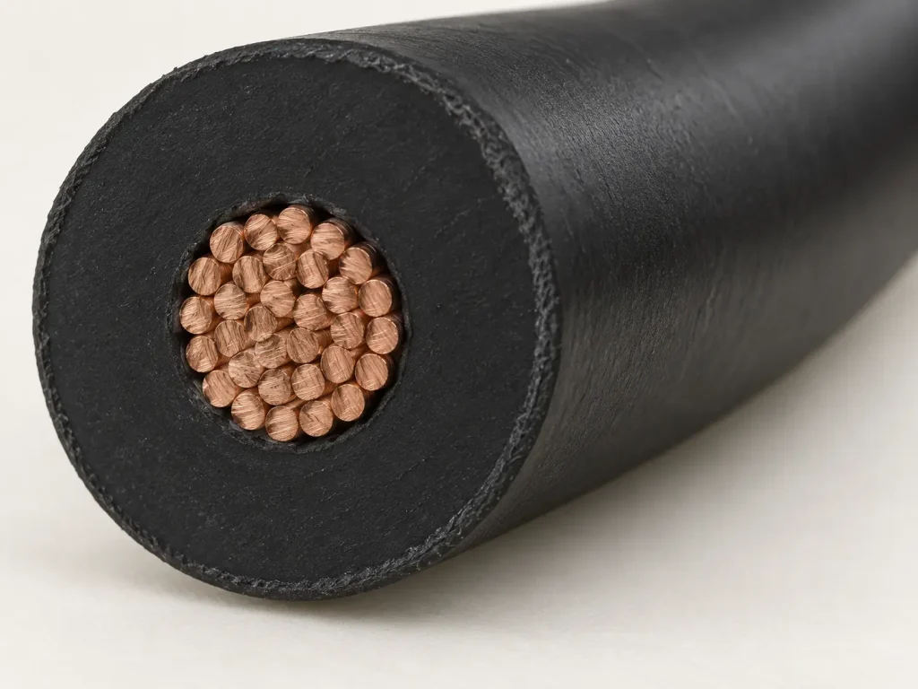
RFQ Checklist for the 20 kV Power-Supply Construction
To request an accurate quotation, please provide:
- UL AWM Style 3239
- Nominal 17 AWG / 1 mm²
- Source-defined 1 mm² cross-section
- 32 / 0.20 mm conductor
- 200°C
- 20 kVDC
- Silicone insulation
- 2.0 mm average wall
- 1.9 mm minimum wall
- 5.3 ±0.1 mm OD
- Black insulation or required colour
- Resistance requirement, if controlled
- Routing-envelope requirement
- Terminal / connector details
- Cut length, if required
- Quantity
- Packaging
- Destination
- Documentation requirements
- Actual power-supply / equipment application context
Applicable RoHS / REACH documentation can be confirmed according to the ordered construction.
See our UL 3239 High Voltage Wire category, our High Voltage Wire range, or our AWM Wire category for related constructions.