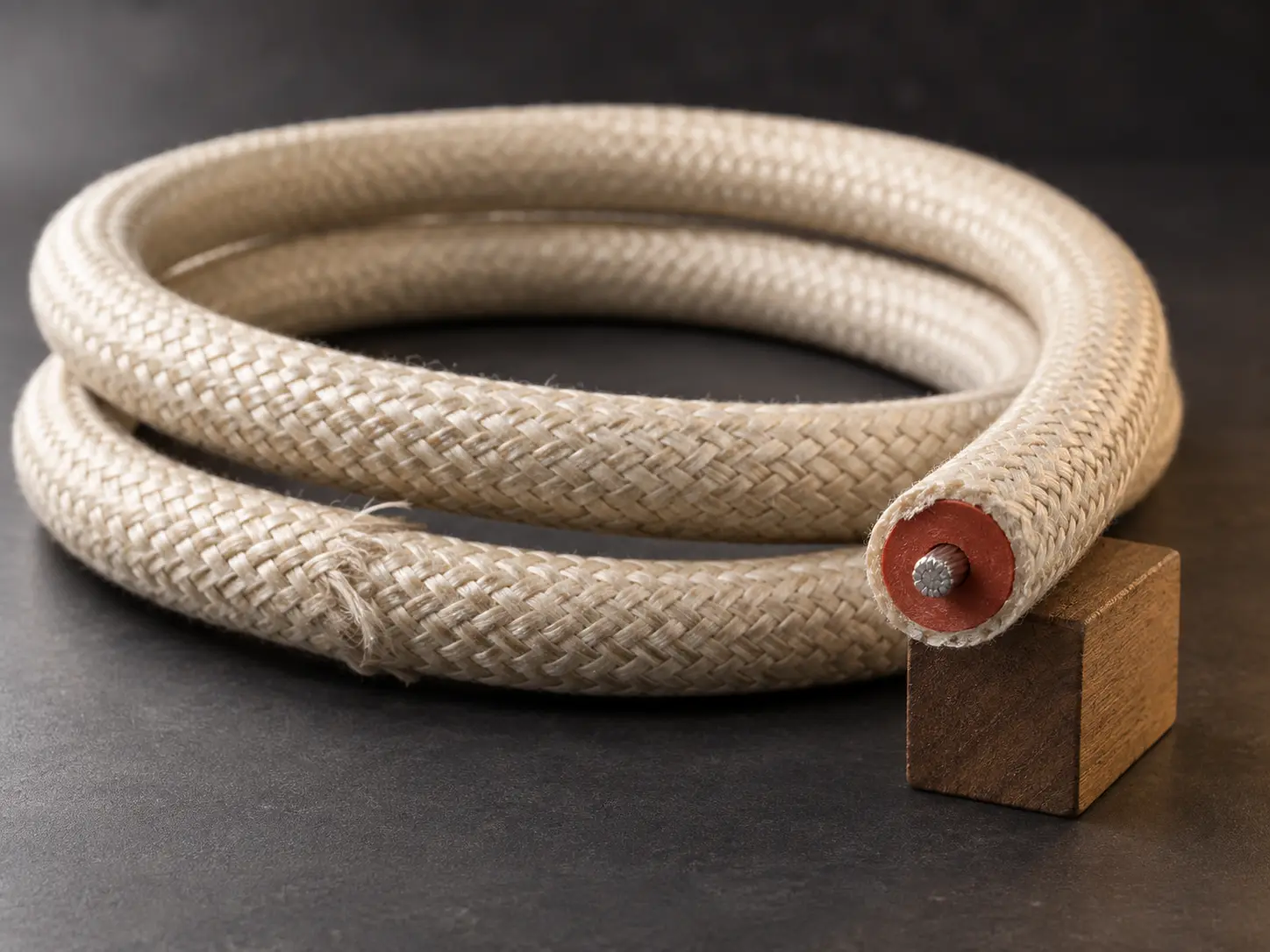
UL 3304 14 AWG Gas Burner Ignition Wire Overview
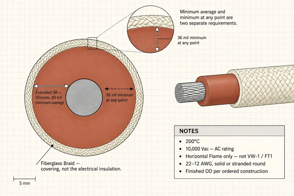
UL AWM Style 3304 is a single conductor with extruded insulation, rated 200°C and 10,000 Vac with Horizontal Flame. The insulation is extruded silicone rubber at 40 mils minimum average thickness and 36 mils minimum at any point, with a fiberglass braid covering over it. The Style conductor range is 22–12 AWG, solid or stranded round.
This page is written for 14 AWG specifically — a concrete conductor size being quoted or evaluated for a protected internal ignition lead in gas burner equipment, rather than the Style range as a whole.
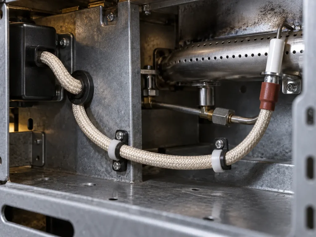
The gas burner application is not a commercial framing here. The official Use names electronic ignition in gas ranges and gas or fuel oil burner systems directly, with one condition attached: the wiring must be protected from damage during handling, installation and servicing of the appliance. That condition travels with the application and is covered in its own section below.
UL 3304 Technical Specifications
| Parameter | Style-level information |
|---|---|
| UL AWM Style | 3304 (UL 758) |
| Description | Single Conductor with Extruded Insulation |
| Page conductor size | 14 AWG |
| Complete Style range | 22–12 AWG |
| Conductor form | Solid or Stranded Round |
| Temperature rating | 200°C |
| Voltage rating | 10,000 Vac |
| Flame | Horizontal Flame |
| Insulation | Extruded SR — Silicone |
| Minimum average insulation thickness | 40 mils |
| Minimum thickness at any point | 36 mils |
| Covering | Fiberglass Braid |
| Official Use | Internal Wiring of Electronic Ignition or similar application in Gas Ranges or Gas or Fuel Oil Burner Systems where protected from damage during handling, installation and servicing of the appliance |
14 AWG Within the Style Range
14 AWG sits inside the verified 22–12 AWG conductor range, and the silicone insulation requirement that applies to it is the same 40 mil minimum average and 36 mil minimum at any point stated for the Style. There is no separate 14 AWG wall thickness, and none is invented here.
What the Style does not provide is a finished outside diameter for a 14 AWG construction. Finished diameter is not calculated by taking a nominal 14 AWG conductor diameter and adding twice the insulation thickness — the braid covering and the actual conductor construction both affect the result, and the figure has to come from the ordered construction rather than from arithmetic on the Style table.
Extruded Silicone Rubber Insulation
The verified insulation is extruded SR — silicone — with the 40 mil minimum average and 36 mil minimum-at-any-point requirements. Those two numbers are separate requirements, not a range: one governs the average across the wall, the other sets a floor at every individual point on it.
This is the primary electrical insulation of the construction, and it is worth stating in those terms in a BOM line rather than as a general description of a high-voltage silicone lead. Where a drawing controls the insulation, quoting the Style values directly is what lets a quotation be matched against it.
Fiberglass Braid Is a Covering, Not the Insulation
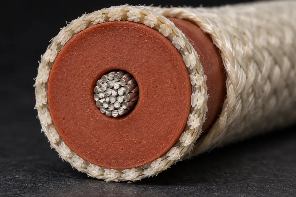
The construction has three parts in a defined order: the conductor, the extruded silicone-rubber insulation, and the fiberglass braid covering over that insulation.
The braid is listed in the Style as a covering. It is not the electrical insulation, and it is not an outer silicone jacket — those are different constructions belonging to different Styles. Describing it accurately in an enquiry matters because “silicone ignition wire with an outer layer” does not identify which construction is meant, and Style 3304 is specific about this one.
The Braid Does Not Replace the Protection Requirement
The official Use requires the wiring to be protected from damage during handling, installation and servicing of the appliance. That requirement is not satisfied by the presence of the fiberglass braid.
No abrasion rating, cut resistance, impact resistance, crush resistance, tensile reinforcement or quantified mechanical durability is claimed for the braid here, because the Style information does not establish any of them. The protection required by the Use has to come from the appliance or burner design.
Protected Routing as a Design Condition
The three activities the Use names are worth reading closely, because they extend past normal operation: handling, installation and servicing. A lead that is well protected in the assembled appliance may still be exposed when a service panel comes off or an ignition module is pulled for replacement.
That makes routing path, clip positions, pass-through points, sharp edges and service access part of the equipment designer’s consideration rather than the wire’s. No clearance dimensions or installation rules are published here — those belong to the appliance design — but describing the actual routing arrangement in an enquiry usually makes the construction question easier to settle.
The 200°C Rating Applies to the Wire
200°C is the verified Style rating for the wire. It is not an approximate figure and not a general high-temperature claim.
It also does not establish that the complete burner enclosure operates continuously at 200°C, that connectors are rated 200°C, that electrodes are, or that every adjacent component may be exposed to that temperature. In an ignition assembly the wire is frequently not the limiting component, and the ratings of the surrounding hardware are separate design questions.
10,000 Vac Is an AC Rating
The verified Style rating is 10,000 Vac. It should be written that way wherever electrical precision matters rather than as a general “10kV high voltage” description.
It is not restated as 10,000 Vdc, a 10kV peak value, an impulse voltage, a spark-test voltage or a dielectric test voltage unless separate construction data supports that value. Those are different parameters and none of them follows from the Style rating.
The Rating Does Not Establish Ignition-System Compatibility
A 10,000 Vac wire rating does not by itself demonstrate compatibility with every 10kV ignition transformer, every pulse waveform, every spark generator, every burner controller or every ignition electrode.
Pulse frequency, spark energy, transformer output waveform and ignition repetition rate are not addressed by the Style information, and no statement about them appears here. Where the circuit condition matters to the selection, the buyer should supply the actual required electrical condition and equipment design rather than inferring suitability from the voltage figure alone.
Solid or Stranded Round
The Style permits solid or stranded round conductors, so stranded is not a default for this page. The required form should come from the equipment drawing or approved BOM and be stated in the enquiry.
Where stranded construction is required, the strand count has to be confirmed separately — “stranded” alone does not identify one strand design. Strand count, individual strand diameter, lay length, conductor diameter and conductor resistance are not published here and are not derived from the Style; a buyer requiring a specific conductor construction should supply it or have it confirmed before production. No flexibility difference or flex-cycle performance is claimed between the two forms.
Conductor Material and Plating Are RFQ Fields
The verified Style information establishes that 14 AWG falls within the permitted range and that solid or stranded round conductors are allowed. It does not establish one universal conductor material or plating for this page.
Copper, bare copper, tinned copper, nickel-plated copper and nickel conductor are none of them assumed here. Where conductor material or finish is controlled by the customer’s drawing or BOM, state it in the enquiry so it can be confirmed against a qualified construction.
Finished Dimensions
Ignition-lead routing frequently passes through constrained areas of a burner assembly, which makes dimensional data commercially relevant even though the Style does not supply it.
Where dimensions are controlled, request the required finished OD, maximum OD, OD tolerance, pass-through or grommet dimensions, terminal-entry dimensions and the required cut length. No numerical finished-diameter value is published on this page.
Termination Requirements
Style 3304 does not define one universal ignition terminal, electrode connector, crimp, boot, strip length, lug or finished lead assembly, and none are invented here.
Where prepared ignition leads are required, supply the terminal part number, connector drawing, strip length, finished lead length and assembly drawing. A request for a prepared lead accompanied only by the Style number cannot be quoted as an assembly.
Current Rating Is Not Published Here
The Style data supplied for 3304 does not provide a universal current-carrying table, and none is published. No amps for 14 AWG, power rating, burner power range, transformer wattage or current capacity appears on this page.
The ignition function and the equipment engineering determine the relevant electrical requirements.
Official AWM Use Boundary
The official Use for Style 3304 is: Internal Wiring of Electronic Ignition or similar application in Gas Ranges or Gas or Fuel Oil Burner Systems where protected from damage during handling, installation and servicing of the appliance.
Gas ranges and fuel oil burner systems are Style-supported use contexts alongside the gas burner systems this page addresses. In all cases the Style remains an AWM internal-wiring construction: it is not external burner cable, field-installed burner wiring, building wire, general high-voltage cable or portable ignition cable, and the protection condition in the Use applies throughout.
What UL 3304 Does Not Automatically Define
- Conductor material and conductor plating
- Strand count, strand diameter and conductor resistance
- Ampacity
- Finished OD and OD tolerance
- Bend radius and flex-cycle life
- Terminal type and connector type
- Lead length and reel length
- MOQ, stock status and production lead time
Common RFQ Mismatches
- Style 3304 requested with no AWG. The Style covers 22–12 AWG; this page is 14 AWG.
- 14 AWG requested without stating solid or stranded. Both forms are permitted.
- Tinned copper assumed. The Style fixes size and form, not conductor material.
- “10kV” written without identifying the AC rating. The verified rating is 10,000 Vac.
- Horizontal Flame read as VW-1 or FT1. Separate classifications requiring separate confirmation.
- Fiberglass braid assumed to remove the protection requirement. The Use condition still applies.
- Finished OD omitted. It cannot be derived from the insulation values.
- Terminal information omitted. Needed before an ignition lead can be quoted.
- Prepared lead requested with only the Style number. An assembly needs a drawing.
Each of these leaves the enquiry matching more than one qualified construction, or matching a wire when the requirement was actually a finished assembly — differences that are considerably cheaper to resolve before quotation.
RFQ Checklist
- UL AWM Style 3304
- Conductor size: 14 AWG
- Solid or stranded
- Conductor material / plating, if controlled
- 200°C requirement
- 10,000 Vac requirement
- Silicone-rubber insulation
- Fiberglass-braid covering
- Finished OD / maximum OD, if controlled
- Braid or wire identification requirement
- Protected internal routing condition
- Gas-burner application
- Terminal / connector details
- Cut length or reel requirement
- Quantity, packaging and destination
- Documentation requirement
Applicable RoHS / REACH documentation can be confirmed according to the ordered construction. UL marking is applied according to the confirmed ordered construction, and material is supplied as UL-recognized component wire under qualified manufacturing scope.