UL 3321 in the Power and Control Sections Inside an Appliance
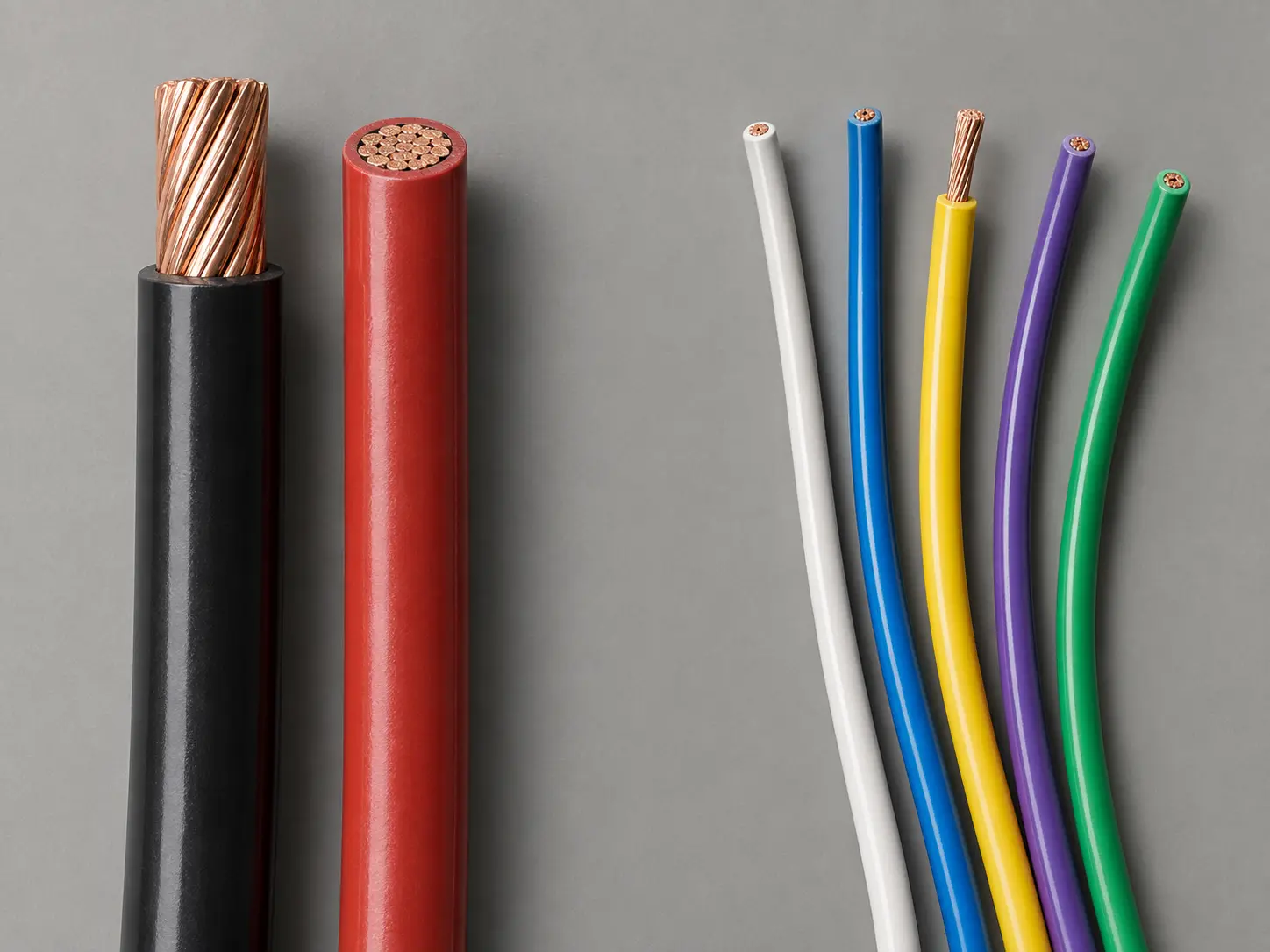
UL AWM Style 3321 is a single conductor with extruded insulation, rated 150°C, 600 Vac and 750 Vdc, with Horizontal Flame. The conductor range is 30 AWG through 4/0 AWG, solid or stranded, with extruded XLPE insulation and an optional treated or untreated braid.
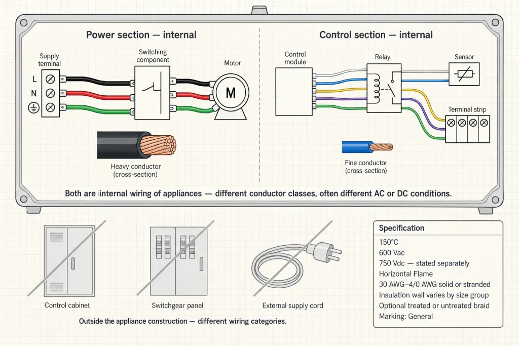
The official Use for Style 3321 is internal wiring of appliances. This page addresses that requirement at the level of electrical function rather than appliance category: the leads that make up the power and control sections located inside the appliance.
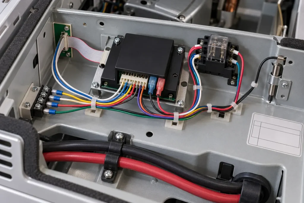
Most appliances of any complexity contain both. A power section handles the load side — supply entry points, switching components, motor or element connections. A control section handles logic and sensing — control modules, switches, relays, sensors, terminal points. The two sections have different conductor sizes, often different voltage conditions, and sometimes different AC or DC conditions, which is why identifying which one a lead belongs to is useful information in an enquiry.
“Power” and “Control” Describe Functions Inside the Appliance
On this page both words describe internal appliance functions. Neither creates a broader UL Use.
The Use names appliances. It does not name equipment, cabinets, panels or systems, so Style 3321 is not presented here as generally covering standalone power-control cabinets, electrical control panels, PLC cabinets, industrial switchgear, motor-control centres, facility distribution equipment, factory automation wiring or machine field wiring. A control module inside an appliance and a control cabinet standing on a factory floor are not the same category of wiring, whatever their functional similarity.
The appliance manufacturer remains responsible for the equipment specification, and specifying Style 3321 for a particular internal section is a design decision made against that specification.
Verified UL Style 3321 Ratings and Construction
| Parameter | Style-level information |
|---|---|
| UL AWM Style | 3321 |
| Construction | Single conductor with extruded insulation |
| Temperature rating | 150°C |
| AC voltage rating | 600 Vac |
| DC voltage rating | 750 Vdc |
| Flame | Horizontal Flame |
| Conductor size range | 30 AWG–4/0 AWG |
| Conductor form | Solid or Stranded |
| Insulation | Extruded XLPE |
| Covering | Optional treated or untreated braid |
| Marking | General |
| Official Use | Internal wiring of appliances |
Size-Dependent Insulation Wall
| Conductor size group | Minimum average thickness | Minimum thickness at any point |
|---|---|---|
| 30 AWG–9 AWG | 30 mils | 27 mils |
| 8 AWG–4 AWG | 45 mils | 40 mils |
| 3 AWG–2 AWG | 60 mils | 54 mils |
| 1 AWG–4/0 AWG | 80 mils | 72 mils |
Insulation-wall requirements increase through the defined conductor-size groups. Style 3321 has no single wall thickness, and a 30 mil figure applies only within the first group.
This matters directly to a page about power and control sections, because the two often sit in different groups. A control lead is frequently a fine conductor in the 30–9 AWG group, while a power-section lead in the same appliance may be heavy enough to fall into the 8–4 AWG group or beyond — two different constructions of the same Style within one product.
Each group states two separate requirements: the first governs the average across the wall, the second sets a floor at every individual point on it.
Internal Power-Section Wiring Is Not External Power Wiring
A power section inside the appliance and the wiring that supplies the appliance are different things.
Style 3321 is single-conductor AWM internal appliance wire. It is not an appliance power cord, a building feeder, branch-circuit wiring, a facility distribution conductor, an external flexible cord or field-installed supply wiring. The point at which the appliance’s own construction ends and the installation wiring begins is the boundary, and the rating on the wire does not move it.
An enquiry mentioning a power lead is therefore worth qualifying as internal, because “appliance power wire” is read differently by different suppliers.
An Appliance Control Section Is Not a Control Panel
The same applies on the control side, and it is worth stating explicitly because the functional description sounds identical.
An internal appliance control section consists of leads between control modules, switches, relays, sensors and terminal points built into the appliance by the manufacturer. Field-installed control-panel wiring is installed to different rules by a different party at a different stage. Style 3321 is not presented here as general control-panel wire, and a control cabinet is not used as an application on this page.
Internal Routing
Routing on this page means routing inside the appliance: fixed internal lead paths, internal power-section lead routing, internal control-section wiring, component-to-component appliance wiring, and drawing-controlled internal routing.
It does not mean plant routing, factory wiring, machine routing, field routing or building routing. Those describe conductors installed outside the appliance’s own construction.
AC and DC Ratings
Style 3321 carries 600 Vac and 750 Vdc as separate verified ratings.
They are kept separate here. 750 Vdc is not restated as 750 Vac, as a generic 600/750V cable designation, as “750V AC/DC”, or as a 600–750V universal rating, and 600 Vac is not characterised as a stronger construction.
This distinction has practical weight on a power and control page. Control sections in modern appliances frequently run on DC, while the power section runs on AC, so the two figures may both be relevant within one product depending on which lead is being specified. State the AC or DC condition applying at the lead position.
The 150°C Rating
150°C is the verified Style-level temperature rating and applies to the wire.
It does not follow that every power or control section operates at 150°C, and no guaranteed continuous service life at that temperature is claimed here. The equipment designer assesses the actual internal temperature at the wire position against the appliance specification. Power sections near a motor or heating element and control sections in cooler parts of the same enclosure can sit at very different temperatures.
Selecting AWG
Style 3321 covers 30 AWG through 4/0 AWG, and no single conductor size is selected for this page.
The appliance electrical design determines the required AWG according to the circuit and the equipment specification. No ampacity value is published here and no required load capability is inferred directly from AWG. The width of the range also means physical dimensions vary substantially across it, so correct AWG identification is required before quotation.
The Optional Braid
A treated or untreated braid is permitted as an optional covering. Not every Style 3321 construction contains one, and it is not mandatory.
Braid material, colour, thickness, abrasion rating, mechanical-strength effect, temperature effect and service-life effect are not established by the Style record and are not stated here. Where a braid is required, it is specified as part of the ordered construction.
Conductor Requirements
Style 3321 establishes the 30 AWG–4/0 AWG range and the solid or stranded form. It establishes nothing else about the conductor.
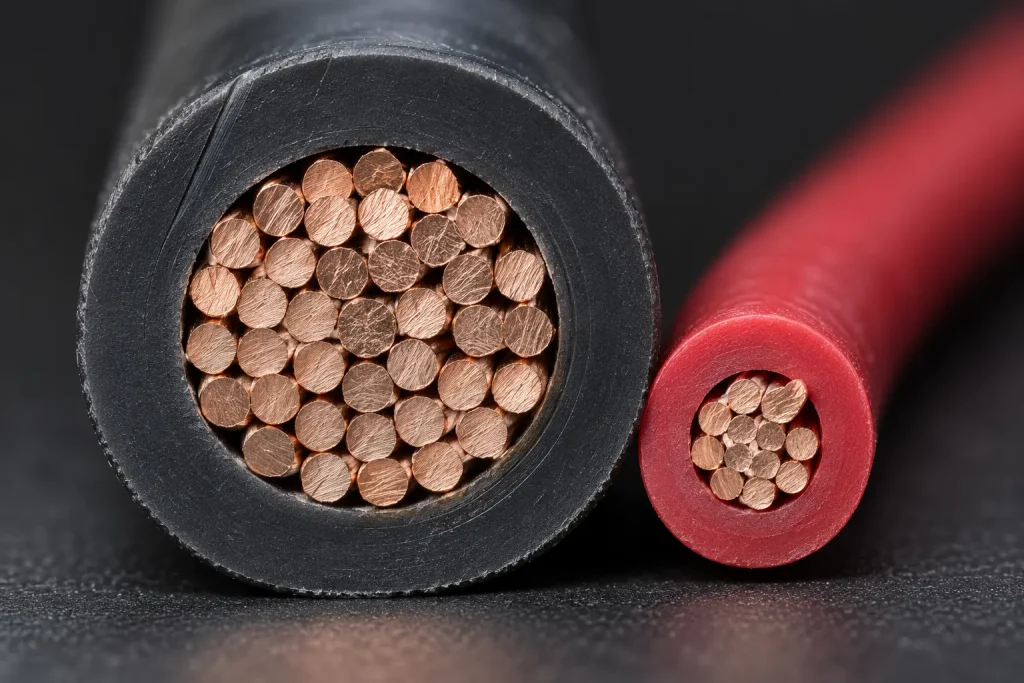
Copper, tinned copper, bare copper, silver-plated copper and nickel-plated copper are none of them established at Style level, and no strand count, strand diameter, conductor diameter, lay length, resistance or ampacity is stated here. Where the appliance drawing requires a conductor material, plating or detailed stranding, each is an RFQ-controlled item.
Dimensional Control
No universal finished outside diameter is published. The Style specifies minimum insulation-wall requirements, not one completed-wire diameter, and finished OD depends on the specific ordered construction.
Where routing space, connector cavities or internal packaging are controlled, specify the AWG, the maximum finished OD, the OD tolerance if controlled, the routing clearance, the terminal interface, the connector interface and the optional braid requirement. Style 3321 is not described here as universally compact, thin-wall, small-diameter or space-saving.
Bulk Wire and a Finished Control Lead
This product is Style 3321 single-conductor wire. Style 3321 itself defines no cut length, strip length, terminal, connector, ferrule, crimp, wire seal, finished control lead or finished appliance harness.
Where processed leads are required, all processing requirements are separately specified and confirmed. Cutting, stripping, crimping, terminals, connectors and harness assembly are not presented here as automatically included.
What Style 3321 Does Not Define
- Conductor material and conductor plating
- Strand count, strand diameter and conductor resistance
- Ampacity
- Finished OD and OD tolerance
- Colour
- Terminal, connector, cut length and strip length
- Harness geometry
- Packaging, reel length, MOQ, stock and lead time
Each requires buyer drawings, ordered-construction confirmation, verified SKU documentation or separate commercial confirmation.
Common Procurement Mismatches
- “UL3321 control wire” requested without confirming the application is inside an appliance.
- Internal appliance control wiring confused with industrial control-panel wiring. Different categories.
- Style 3321 requested with no AWG. Four insulation groups sit inside the range.
- Tinned copper assumed from the Style number. Conductor material is not set at Style level.
- 30 mil insulation assumed for every conductor size. It applies to the 30–9 AWG group only.
- Braid assumed to be mandatory. The covering is optional.
- 750 Vdc read as 750 Vac. The AC rating is 600 Vac.
- One universal finished OD assumed. OD depends on size, construction and braid.
- Bulk wire assumed to include terminals or connectors.
- Internal power-section wire not distinguished from an external appliance power cord.
RFQ Checklist
- UL AWM Style 3321 requirement
- Required AWG within 30 AWG–4/0 AWG
- Solid or stranded requirement
- Required conductor material
- Required conductor finish or plating
- Detailed stranding, if controlled
- Insulation colour
- Optional braid requirement
- Finished OD or maximum OD, if controlled
- Appliance type
- Whether the wire is in a power or control section
- Internal installation location
- Required AC or DC condition
- Temperature requirement at the wire location
- Customer drawing
- Existing wire specification
- Cut length, if applicable
- Strip length
- Terminal or connector interface
- Marking requirement
- Quantity
- Packaging requirement
- Destination
- Required compliance documentation
These are buyer-controlled RFQ inputs. No combination is presented as automatically available.
Substitution
Different UL AWM Styles have independent ratings, constructions, conductor ranges, coverings and official Uses. No Style is presented here as automatically interchangeable with Style 3321, and none is suggested on the basis of insulation-family preference alone.
Any substitution is evaluated against the actual appliance specification across the required Style, the official Use, the temperature and voltage ratings, the AWG, the conductor construction, the insulation system, the covering, the dimensions and the termination requirements.
UL Marking and Documentation
Material is supplied as UL-recognized component wire where supplied under qualified manufacturing scope, and UL marking is applied according to the confirmed ordered construction. The Style-level marking designation is General.
CSA AWM, FT1, VW-1 and dual UL / CSA certification are not claimed here; any additional certification depends on the ordered construction. Applicable RoHS / REACH documentation can be confirmed according to the ordered construction.
Flame Classification
The verified Style-level flame designation is Horizontal Flame. VW-1 and FT1 are separate classifications and are not claimed here; Horizontal Flame is not converted into either. Any separately confirmed vertical-flame construction remains order-specific.