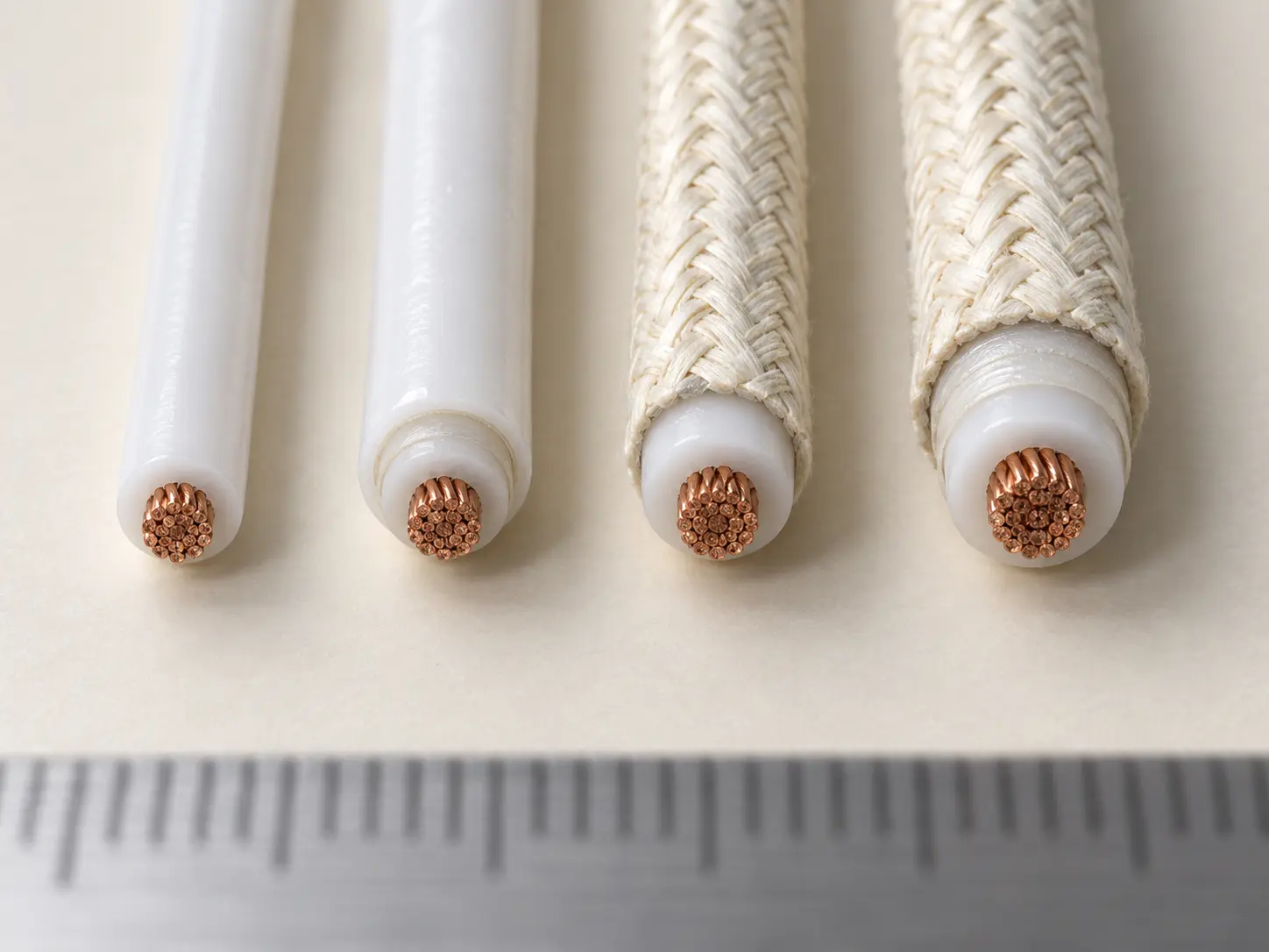
UL 1659 PTFE/TFE Wire for Dimension-Controlled Internal Assemblies
UL AWM Style 1659 is a single conductor with extruded PTFE / TFE insulation, rated 250°C and 600 Vac with Horizontal Flame. The Style conductor range is 26 AWG through 4/0 AWG, solid or stranded round.
This page focuses commercially on the 26–10 AWG group, which carries the Style’s 20 mil minimum-average and 18 mil minimum-at-any-point insulation requirement, for compact high-temperature electrical assemblies where internal dimensions are controlled by the equipment drawing.
Compact assembly wire is a commercial positioning term rather than the formal UL Style name. Style 1659 certifies no compact dimension, space saving, minimum finished OD, routing density or assembly efficiency. Suitability for a compact assembly is determined from the ordered conductor construction, the finished OD, the tolerance and the equipment geometry — which is what most of this page is about.
Verified UL Style 1659 Specification
| Parameter | Style-level information |
|---|---|
| UL AWM Style | 1659 |
| Construction | Single conductor with extruded insulation |
| Temperature | 250°C |
| Voltage | 600 Vac |
| Flame | Horizontal Flame |
| Optional rating | Oil Res 80°C |
| Optional rating | Gasoline Resist |
| Conductor range | 26 AWG–4/0 AWG |
| Conductor form | Solid or Stranded Round |
| Insulation | PTFE / TFE |
| 26–10 AWG insulation | 20 mil average / 18 mil minimum |
| 8–2 AWG insulation | 30 mil average / 27 mil minimum |
| 1–4/0 AWG insulation | 45 mil average / 40 mil minimum |
| Optional covering | Mica tape wrap |
| Optional braid | Treated glass braid |
| Marking | General |
| Official Use | Internal wiring |
This product page focuses commercially on the 26–10 AWG group for compact dimension-controlled internal assemblies. The full UL 1659 Style range remains 26 AWG through 4/0 AWG, and the larger groups are part of the Style even though they are not this page’s purchasing intent.
Note on the thickness table: the official groups run 26–10 AWG, then 8–2 AWG, then 1–4/0 AWG. There is no 9 AWG row. Where 9 AWG is requested, the applicable qualified construction should be confirmed before quotation rather than taken from either neighbouring group.
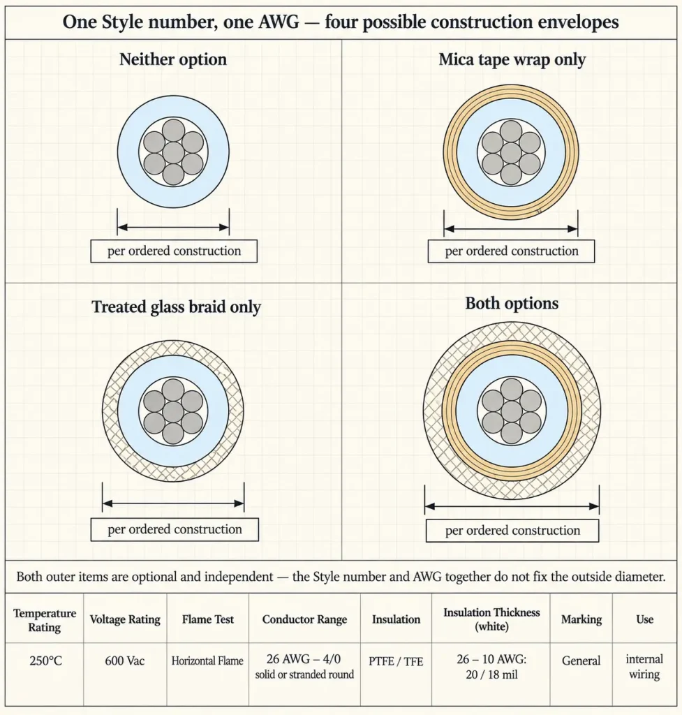
Four Possible Construction Envelopes Under One Style Number
This is the point that matters most for a dimension-controlled design, and it is easy to miss.
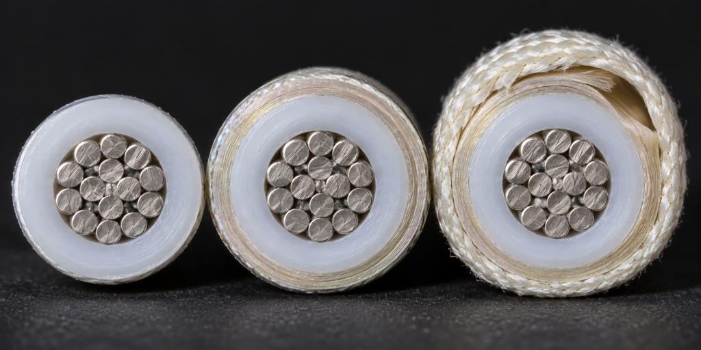
Style 1659 carries two independent optional outer items: a mica tape wrap and a treated glass braid. Each is optional, and they are separate fields rather than alternatives. A construction may therefore have neither, the mica tape only, the braid only, or both.
That means one Style number at one AWG can correspond to four different construction envelopes before conductor variation is even considered. For a buyer working to a maximum OD, the Style number and the AWG together do not narrow the outside diameter to a single figure — which makes checking the ordered construction essential rather than procedural.
Where a compact assembly requires either optional item, its dimensional effect belongs in the review alongside the requirement itself.
What the 20 Mil Group Does and Does Not Establish
The 26–10 AWG group carries a verified 20 mil minimum average insulation requirement with 18 mils minimum at any point. That figure is the factual basis for this page’s smaller-gauge, dimension-controlled positioning.
It is a requirement on the insulation, not on the wire. It does not establish that Style 1659 is inherently compact, that it has the smallest finished OD, that PTFE automatically saves space, that 20 mil insulation guarantees a compact cable, or that the wire fits every compact enclosure.
Nor does it establish a small OD on its own, because the conductor sits inside it. Two constructions in the same insulation group with different conductor diameters produce different finished wires, and the insulation figure is the same in both cases.
Finished Outside Diameter
Style 1659 does not define one universal finished OD, and none is calculated here from AWG plus minimum insulation wall.
Actual finished OD depends on the actual conductor diameter, the solid or stranded construction, the strand configuration, the actual insulation extrusion, whether the optional mica tape is present, whether the optional treated glass braid is present, and manufacturing tolerance.
For a compact equipment RFQ, the dimensional information to supply is:
- Maximum permitted finished OD
- OD tolerance
- Routing-channel dimensions
- Terminal-entry dimensions, where controlled
No OD value is published or invented on this page. With those four figures in the enquiry, a construction can be checked against the drawing rather than assumed to fit.
The Three Insulation Groups
The requirement changes substantially across the Style: 20 mils minimum average for 26–10 AWG, 30 mils for 8–2 AWG, and 45 mils for 1–4/0 AWG, each with its own minimum-at-any-point figure as a separate requirement.
A 20 mil value therefore describes the first group only. It is not applied here to all Style 1659 sizes, 30 mil is not applied to all larger sizes, 45 mil is not applied to all constructions, and no nominal insulation thickness is invented.
PTFE / TFE
The verified Style insulation designation is PTFE, TFE, and the technical specification on this page keeps both. The commercial description may say PTFE wire, since that is how the product is searched for, but the Style-level reference to TFE is not erased.
PFA, FEP, ETFE and PVDF are not Style 1659 insulation options and are not introduced here.
250°C, 600 Vac and Flame
250°C is a verified Style rating and is stated as a rating. It is not written here as 250°C continuous service, continuous 250°C operation, a guaranteed lifetime at 250°C, repeated thermal cycling at 250°C, or long-term 250°C durability — none of those is established by the available data.
The voltage rating is 600 Vac, used accurately and not converted into 600 Vdc, 600V AC/DC, 600/1000V or 1000V.
The flame designation is Horizontal Flame. VW-1, FT1, vertical flame and any other named flame test are not claimed here, and any additional flame requirement is separately confirmed.
Conductor Requirements and Actual Conductor Diameter
Style 1659 establishes 26 AWG through 4/0 AWG, solid or stranded round. It establishes nothing else about the conductor.
Copper, tinned copper, bare copper, silver-plated copper and nickel-plated copper are none of them established at Style level, and no strand count, strand diameter, lay length or conductor resistance is stated.
On a dimension-controlled page one of these deserves particular attention: the actual conductor diameter. A stranded conductor and a solid conductor of the same AWG do not occupy the same space, and strand configuration affects the result further. For a compact assembly RFQ, conductor material, finish, detailed stranding and actual conductor diameter are confirmed according to the ordered construction rather than treated as settled by the AWG.
Optional Mica Tape Wrap
Mica tape is optional and is not presented here as standard. No claim is made that it provides 450°C capability, fire survival, circuit integrity, arc resistance, mechanical protection or a smaller OD.
Where a compact assembly requires mica tape, its additional dimensional effect is part of the finished-OD review — the requirement and the space it occupies are two separate things to confirm.
Optional Treated Glass Braid
The treated glass braid is likewise optional, not mandatory. No abrasion resistance, mechanical protection, higher thermal rating, improved flexibility or smaller OD is claimed for it.
For a dimension-controlled assembly, an optional braid changes the final construction envelope and is confirmed when relevant, alongside the maximum OD it has to sit within.
Optional Oil and Gasoline Resistance
Style 1659 includes an optional Oil Res 80°C rating and an optional Gasoline Resist rating. Not all Style 1659 constructions carry either.
Where oil resistance is required, the buyer requests and confirms the applicable optional rating. The gasoline resistance rating is treated the same way and is not converted into a broad chemical-resistance claim covering other fluids or conditions.
Compact Assembly as an Application Context
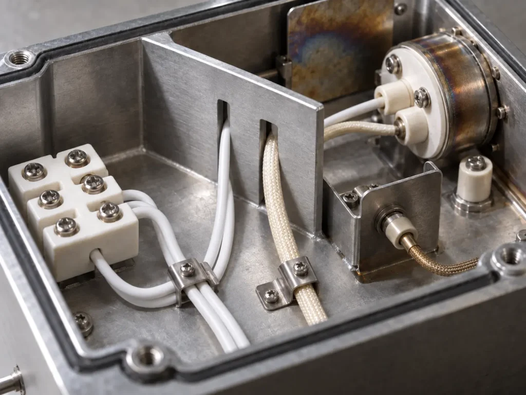
The buyer contexts this page addresses are compact electrical assemblies, space-constrained internal component layouts, enclosed electronic or electrical assemblies, internal wiring channels with controlled clearances, and equipment where both the temperature rating and the physical wire dimensions have to be reviewed.
These are procurement contexts. UL does not separately certify each named equipment application, and no such certification is implied.
The official Use is internal wiring. Style 1659 is not building wiring, field wiring, branch circuits, conduit, tray, raceway, external equipment cable, portable cord or power cord.
Bend Geometry in a Tight Enclosure
No minimum bend radius, flexibility claim, flex-cycle figure, continuous-flex rating or routing-flexibility statement appears here, because the Style data provides none.
A compact enclosure also does not mean the wire is suitable for repeated movement — tight space and motion are separate conditions. Where bend geometry is critical to the assembly, it is treated as an RFQ and design-confirmation item rather than resolved from the Style.
Current Rating and Material Performance
No universal ampacity or current rating is published, because Style 1659 establishes none and AWG alone is insufficient to define equipment current capability. No ampacity table appears here.
No figure is offered for dielectric strength beyond 600 Vac, corona resistance, partial-discharge performance, arc resistance, capacitance, impedance, abrasion resistance, cut-through performance, thermal cycling, service life, UV resistance or water resistance. None of these is inferred from PTFE material reputation.
Dimensional RFQ Information
- Required AWG
- Solid or stranded round conductor
- Conductor material, finish or plating
- Stranding, if controlled
- Required conductor diameter, if controlled
- 250°C requirement and 600 Vac requirement
- PTFE / TFE construction requirement
- Maximum finished OD and OD tolerance
- Routing-channel clearance and terminal-entry clearance
- Optional mica tape required: yes / no
- Optional treated glass braid required: yes / no
- Optional Oil Res 80°C required: yes / no
- Optional Gasoline Resist required: yes / no
- Colour and marking
- Quantity, packaging and destination
- Required compliance documentation
None of these values is invented here. The four optional items in particular each need their own answer, since any of them changes what is being quoted.
What Style 1659 Does Not Define
- Conductor material and conductor plating
- Strand count, strand diameter and actual conductor diameter
- Finished OD and OD tolerance
- Conductor resistance, ampacity and current rating
- Bend radius and flex life
- Colour
- Terminal, connector and cut length
- MOQ, stock and lead time
Each comes from the customer drawing, verified SKU documentation, the applicable qualified construction, or commercial confirmation.
Common Procurement Errors
- 20 mil insulation assumed for all Style 1659 sizes. It applies to 26–10 AWG only.
- 20 mil insulation read as a guarantee of compact finished OD. It is an insulation requirement.
- Actual conductor diameter ignored. Solid and stranded of the same AWG differ.
- Optional mica tape ignored when checking OD.
- Optional glass braid ignored when checking OD.
- A 9 AWG thickness invented. The official table has no 9 AWG entry.
- Stranded tinned copper assumed. Conductor material is not set at Style level.
- Every construction assumed Oil Res 80°C. It is optional.
- Every construction assumed Gasoline Resist. Also optional.
- All PTFE wire treated as interchangeable.
- A universal ampacity published from AWG alone.
- Wire selected from the Style number without checking maximum OD and tolerance.
Style Selection
Different UL AWM Styles have different temperature ratings, voltage ratings, Uses, construction requirements, dimensions and optional features. No Style is presented here as a substitute for another on the basis of polymer family, and no material-family superiority claim is made against PVC, silicone or other constructions.
Any alternative is reviewed against the customer’s actual specification, including the dimensional constraints that define this page.
UL Marking and Documentation
Material is supplied as UL-recognized component wire where supplied under qualified manufacturing scope, and UL marking is applied according to the confirmed ordered construction. The Style-level marking designation is General.
CSA AWM, FT1, VW-1 and dual UL / CSA certification are not claimed here; any additional certification depends on the ordered construction. Applicable RoHS / REACH documentation can be confirmed according to the ordered construction.