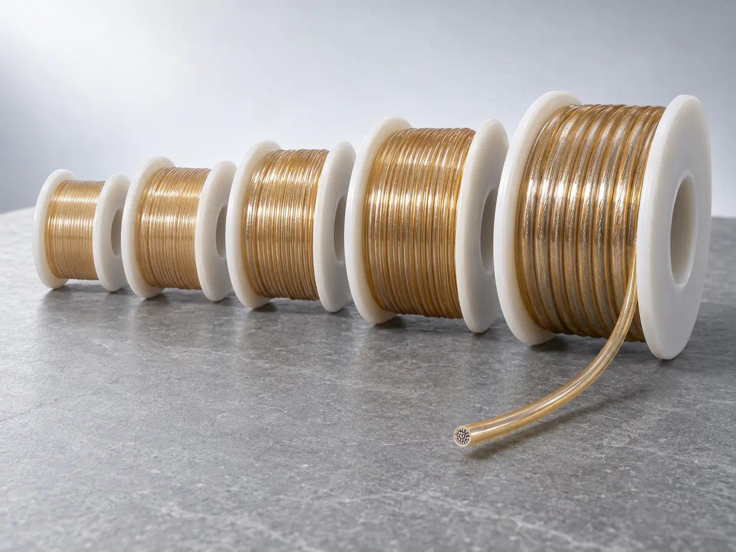
UL 1332 200°C 300V FEP 30–10 AWG Wire with 13 mil Insulation
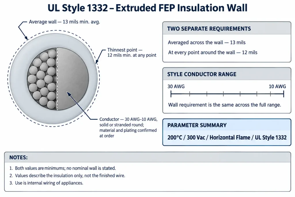
This page covers the base construction of UL AWM Style 1332: a single conductor with covering, insulated with extruded FEP at 13 mils minimum average and 12 mils minimum at any point, rated 200°C and 300 Vac with a Horizontal Flame designation, in a conductor range of 30 AWG–10 AWG, solid or stranded round, for internal wiring of appliances.
It is written for appliance and equipment OEM engineering and procurement teams whose drawing, BOM or wire specification calls for Style 1332 in its standard insulated form, without an optional outer covering and without an optional fluid-resistance designation as the deciding requirement.
The insulation wall is what this page is built around, because it is the part of the Style record most often quoted loosely. The two figures are separate requirements, they apply across the whole conductor range, and they describe the insulation only, not the finished wire.
Confirmed UL Style 1332 Construction
| Parameter | Requirement |
|---|---|
| UL AWM Style | 1332 |
| Description | Single Conductor with Covering |
| Temperature | 200°C |
| Voltage | 300 Vac |
| Flame | Horizontal Flame |
| Conductor Range | 30 AWG–10 AWG |
| Conductor Construction | Solid or stranded round |
| Insulation | Extruded FEP |
| Insulation Thickness | 13 mil minimum average / 12 mil minimum at any point |
| Optional Covering | Extruded FEP, 2 mil or heavier |
| Alternative Optional Covering | Glass braid, 7 mil or heavier |
| Optional Rating | Oil Resistant 80°C |
| Optional Rating | Gasoline Resistant |
| Marking | General |
| Use | Internal wiring of appliances. |
| Optional Tag Information | Gasoline immersion; gasoline vapor; 80°C in oil; and / or 600 volts peak for electronic use only, where applicable to the confirmed ordered construction |
| RoHS / REACH | Applicable RoHS / REACH documentation can be confirmed according to the ordered construction |
Nine points to clarify about the table above:
- 13 mil minimum average and 12 mil minimum at any point are two independent requirements, not a range and not a nominal wall.
- The insulation requirement is the same across the full 30 AWG–10 AWG range; the record publishes no size-dependent wall table for this Style.
- The insulation is extruded FEP. PTFE, PFA, ETFE, PVC, XLPE, silicone and mica are different materials and are not this Style.
- The two covering entries are alternatives, each optional, each supplied only where the ordered construction supports it.
- The oil and gasoline resistance ratings are optional and independent of one another.
- The oil designation is stated at 80°C, separate from the 200°C Style temperature rating.
- 600 volts peak for electronic use only is a tag indication, not the normal voltage rating, which remains 300 Vac.
- Conductor material, plating, strand count, strand diameter and lay length are not defined by the Style.
- Finished OD, OD tolerance, conductor resistance, metric cross-section and ampacity are not defined by the Style.
13 mil Minimum Average FEP Insulation
The Style defines the extruded FEP insulation by two values that work together. The average thickness of the wall must be at least 13 mils. Separately, the wall must be at least 12 mils at every point around the conductor.
These measure different things. The first is an averaged figure for the wall, so a construction satisfies it across the section as a whole. The second is a floor applied locally: no single point of the wall may fall below it, whatever the average reads. A construction that met only the 13 mil average while thinning below 12 mils somewhere on the circumference would not satisfy the requirement, and a construction held at 12 mils throughout would not satisfy the average.
Both are minimums rather than targets. The record states no nominal wall, no tolerance band and no manufacturing allowance, so this page does not supply one: an actual construction may sit above these figures, and how far above is a property of that construction rather than of the Style.
Neither value produces a finished outer diameter. Finished OD depends on the conductor material and form, the actual conductor diameter, whether an optional covering is applied, the FEP extrusion and manufacturing tolerance. Adding a generic AWG conductor diameter to the insulation minimum does not give a valid product dimension, and this page publishes no AWG-to-diameter, conductor resistance or current table for that reason. Where connector entry, sleeve fit or routing clearance is controlled by the design, state a maximum finished OD and an OD tolerance in the RFQ so the proposed construction can be checked against the actual requirement.
FEP, fluorinated ethylene propylene, belongs to the fluoropolymer family, but the product identity here remains FEP specifically. Properties published for other fluoropolymers are not transferred to this Style, and beyond the optional ratings noted below the record states no chemical, solvent, moisture, dielectric or low-friction property, so none is attributed to the insulation.
30 AWG to 10 AWG Conductor Range
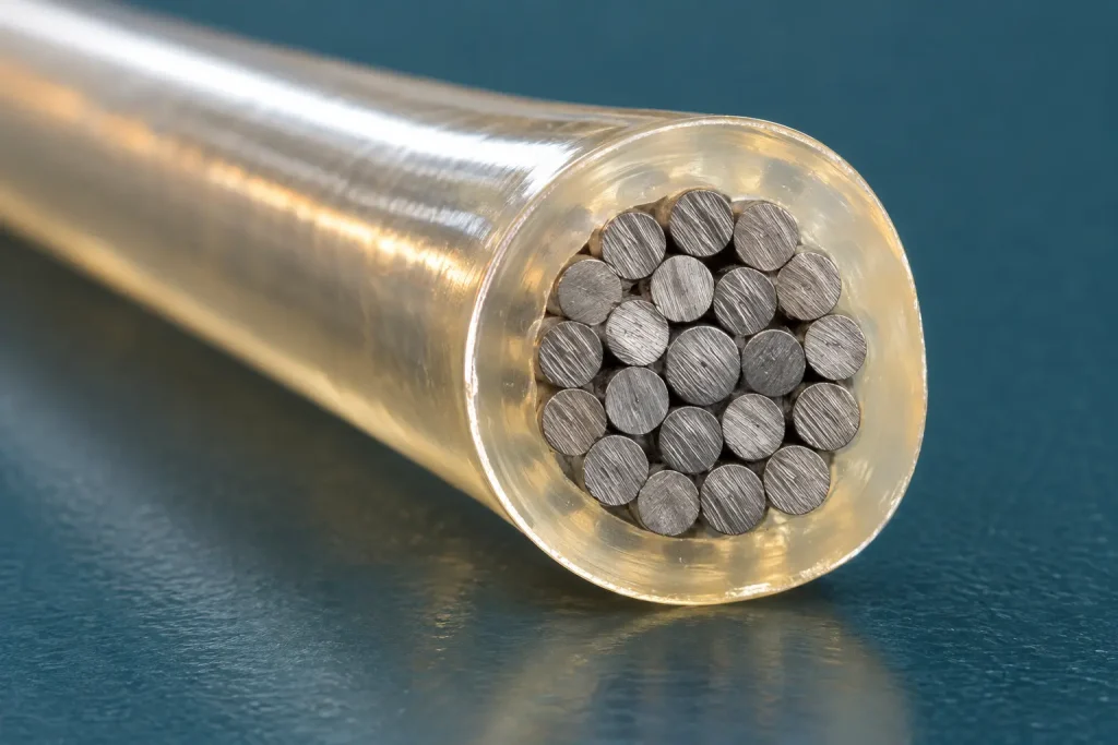
The confirmed conductor range is 30 AWG through 10 AWG, solid or stranded round. Both forms are permitted across the range, and the Style presets neither, so a drawing that controls the conductor form should state which is required.
Because the insulation requirement does not step with conductor size, the same wall governs both ends of the range. The proportion differs considerably: at 30 AWG the wall is a large share of the finished wire, while at 10 AWG it is a comparatively slim layer over a substantial conductor. That is a description of the requirement rather than a performance statement, and no dielectric, mechanical or handling property is inferred from it here.
The Style states nothing further about the conductor. Material, plating, strand count, strand diameter, lay construction, conductor resistance and any metric cross-section are SKU-specific characteristics. Where the buyer’s drawing controls any of them, they are confirmed separately during RFQ review and checked against the proposed construction. No stranding class or flexibility grade is applied to Style 1332 here, since the record contains none.
Conductor size also assigns no circuit function or current capacity. The record gives no ampacity, and none is inferred from conductor size, the 200°C rating or the 300 Vac rating. Current-carrying capacity is evaluated through the buyer’s equipment design and the applicable approval process. Style scope is likewise not availability: a given size and construction is confirmed per enquiry.
300 Vac and the Optional 600 Volts Peak Tag
The normal Style rating is 300 Vac. That is the voltage rating carried by a Style 1332 construction, and it is the figure that belongs in a specification.
Separately, where applicable to the confirmed ordered construction, the tag may indicate 600 volts peak for electronic use only. This is a tag indication with two qualifiers attached, and both stay with it whenever it is cited. It is not a working-voltage rating, it does not replace or raise the 300 Vac rating, and it does not make Style 1332 a 600 V wire.
The record gives no DC rating, so none is stated or derived. The two concepts are kept distinct throughout an enquiry: the voltage requirement is stated against the 300 Vac rating, and any need for the peak tag indication is listed separately as a marking and construction question.
Optional Ratings and Optional Covering
Four options appear in the record, and each is secondary to the base construction this page addresses. None is included unless the ordered construction supports it and the buyer specifies it.
An Oil Resistant 80°C designation is optional, with its temperature belonging to that rating rather than following the 200°C Style rating. A Gasoline Resistant designation is optional and independent of the oil rating; neither implies the other, and neither is a general chemical compatibility statement or an indication that the Style is designated for any particular fuel system component. The applicable tag wording is confirmed according to the ordered construction.
On the construction side, an extruded FEP covering of 2 mils or heavier, or a glass braid of 7 mils or heavier, may be applied. They are alternatives rather than a combined build, and each figure is a minimum for that form alone, never added to the 13 mil insulation requirement to produce a single wall figure. The record assigns neither covering a function, so no dielectric margin, abrasion resistance, mechanical protection, shielding, temperature increase or chemical performance is claimed for either here.
Where a fluid-resistance designation or an outer covering is the deciding requirement for a project, the dedicated pages linked at the end address those constructions in more detail.
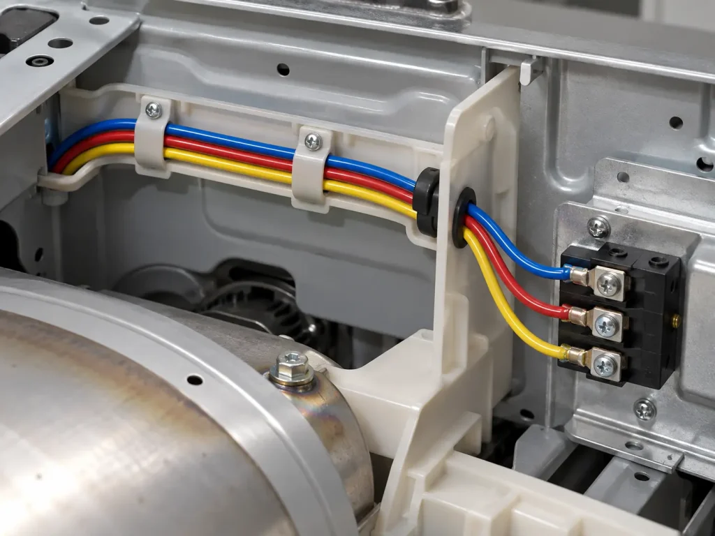
Internal Wiring of Appliances
The official Use is “Internal wiring of appliances.” This page keeps that wording and does not extend it to signal or instrumentation cable, sensor leads, motor leads, building wire, field wiring, branch circuits, conduit wiring, tray cable, external wiring, portable cord, facility power distribution or outdoor wiring.
In practice the Style is matched to a requirement from the drawing rather than from the Style number alone. A BOM line calling for Style 1332 identifies the construction family; the internal wiring position within the appliance, the conductor size and form, and any optional rating or covering then complete the specification. Where an existing wire is being replaced, describing the installed construction in the enquiry allows the proposed one to be compared against it directly.
Compliance of a finished appliance or assembly is established at the equipment level and is not conferred by the Style designation of one internal wire.
How to Specify UL 1332 in an RFQ
A Style designation is a construction requirement, not a complete purchase specification. A complete enquiry states:
- the UL AWM Style 1332 requirement
- the required AWG within 30 AWG–10 AWG
- solid or stranded round construction
- conductor material and plating, if controlled by the drawing
- insulation colour
- whether an optional Oil Resistant 80°C designation is required
- whether an optional Gasoline Resistant designation is required
- whether an optional extruded FEP covering or glass braid is required
- marking requirements
- the drawing or BOM
- documentation requirements
- quantity and packaging
- destination and Incoterm
UL Style data alone does not define finished OD, OD tolerance, conductor resistance, ampacity, strand count or commercial terms. Those are confirmed separately against the ordered construction. Marking requirements and the applicable UL marking are likewise confirmed according to the ordered construction.
Pricing and commercial terms depend on the confirmed conductor size, conductor construction, insulation colour, optional ratings, optional covering, marking requirements, documentation, packaging, quantity, destination and Incoterm. Final commercial terms are confirmed after RFQ review.
Page Scope
This page addresses UL 1332 at 200°C and 300 Vac in 30–10 AWG, solid or stranded round, with 13 mil minimum average and 12 mil minimum at any point extruded FEP insulation, for internal wiring of appliances. An enquiry that turns on the base insulated construction and its wall requirement belongs here.
Where the deciding requirement is an optional oil or gasoline resistance designation, or an optional outer covering, the dedicated pages below address those constructions specifically, and broader Style 1332 questions are better answered from the category and core product pages.
What Style 1332 Does and Does Not Define
Style 1332 defines:
- 200°C temperature rating and 300 Vac voltage rating
- Horizontal Flame
- a single conductor with covering, conductor range 30 AWG–10 AWG, solid or stranded round
- extruded FEP insulation, 13 mil minimum average / 12 mil minimum at any point
- an optional covering of extruded FEP at 2 mils or heavier, or glass braid at 7 mils or heavier
- optional Oil Resistant 80°C and optional Gasoline Resistant designations
- Marking: General
- Use: Internal wiring of appliances.
- the tag information for gasoline immersion, gasoline vapor, 80°C in oil, and / or 600 volts peak for electronic use only
Style 1332 does not universally define:
- conductor material, plating, strand count, strand diameter or lay length
- a nominal insulation wall or a manufacturing tolerance
- finished OD, OD tolerance, bend radius, flex cycles or flex class
- conductor resistance, ampacity, current rating or metric cross-section
- a normal 600 V rating or any DC rating
- a function or performance for either covering form
- chemical or solvent compatibility beyond the optional ratings and tag indications as worded
- colour, reel length, MOQ, stock, lead time, production capacity or shipping term
Common Procurement Errors
- Quoting 13 mil as a nominal wall, or omitting the 12 mil minimum-at-any-point requirement.
- Treating the two figures as a tolerance band rather than two separate requirements.
- Assuming a heavier wall applies at larger conductor sizes.
- Deriving a finished OD by adding the insulation minimum to a generic AWG conductor diameter.
- Publishing conductor resistance or ampacity tables as Style data.
- Assuming the conductor is bare or tinned copper, or that all Style 1332 is stranded.
- Writing “200°C continuous”, or claiming a higher temperature rating.
- Describing Style 1332 as a 600 V wire, or dropping “for electronic use only” from the tag wording.
- Treating an optional covering or an optional fluid-resistance designation as standard.
- Adding the covering minimum to the insulation minimum to produce one wall figure.
- Substituting PTFE, PFA, ETFE or another material under the Style 1332 name.
- Extending internal wiring of appliances into signal, motor, installation or external wiring.
RFQ Information to Confirm
Style and ratings
- UL AWM Style 1332 requirement
- 200°C temperature rating requirement
- 300 Vac voltage rating requirement
- Required AWG within 30 AWG–10 AWG
- Whether the optional Oil Resistant 80°C designation is required
- Whether the optional Gasoline Resistant designation is required
- Whether the optional peak tag indication is required
Conductor and construction
- Solid or stranded round construction
- Conductor material and plating requirement, if controlled by the drawing
- Strand construction, if controlled
- Maximum conductor resistance, if controlled
- Whether an optional extruded FEP covering or glass braid is required
- Maximum OD and OD tolerance, if controlled
Identification and application references
- Insulation colour
- Marking requirements
- Appliance internal wiring location
- Drawing, BOM or equipment specification
Commercial
- Quantity and packaging
- Destination and Incoterm
- Requested UL marking and compliance documents, including any RoHS / REACH documentation requirement
UL Marking and Documentation
Supplied wire is UL-recognized component wire where supplied under a qualified manufacturing scope, with UL marking according to the confirmed ordered construction. The Style record lists Marking as General, and marking requirements should be confirmed according to the ordered construction.
Applicable RoHS / REACH documentation can be confirmed according to the ordered construction. CE, CSA, FT1, VW-1, CPR, VDE, DIN, EN, IEC and dual UL/CSA designations are not claimed here. Commercial, origin, compliance and transport documents are identified during quotation and confirmed according to the order.
Internal Links
- UL 1332 FEP Wire — category page for broad Style 1332 enquiries
- Fluoropolymer Wire
- AWM Wire
- UL 1332 with optional oil and gasoline resistance — separate page for the optional fluid-resistance requirement
- UL 1332 with optional FEP covering or glass braid — separate page for the optional outer-covering construction