UL 1015 in 30 AWG and 8 AWG for UAE and Saudi Arabia Sourcing
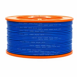
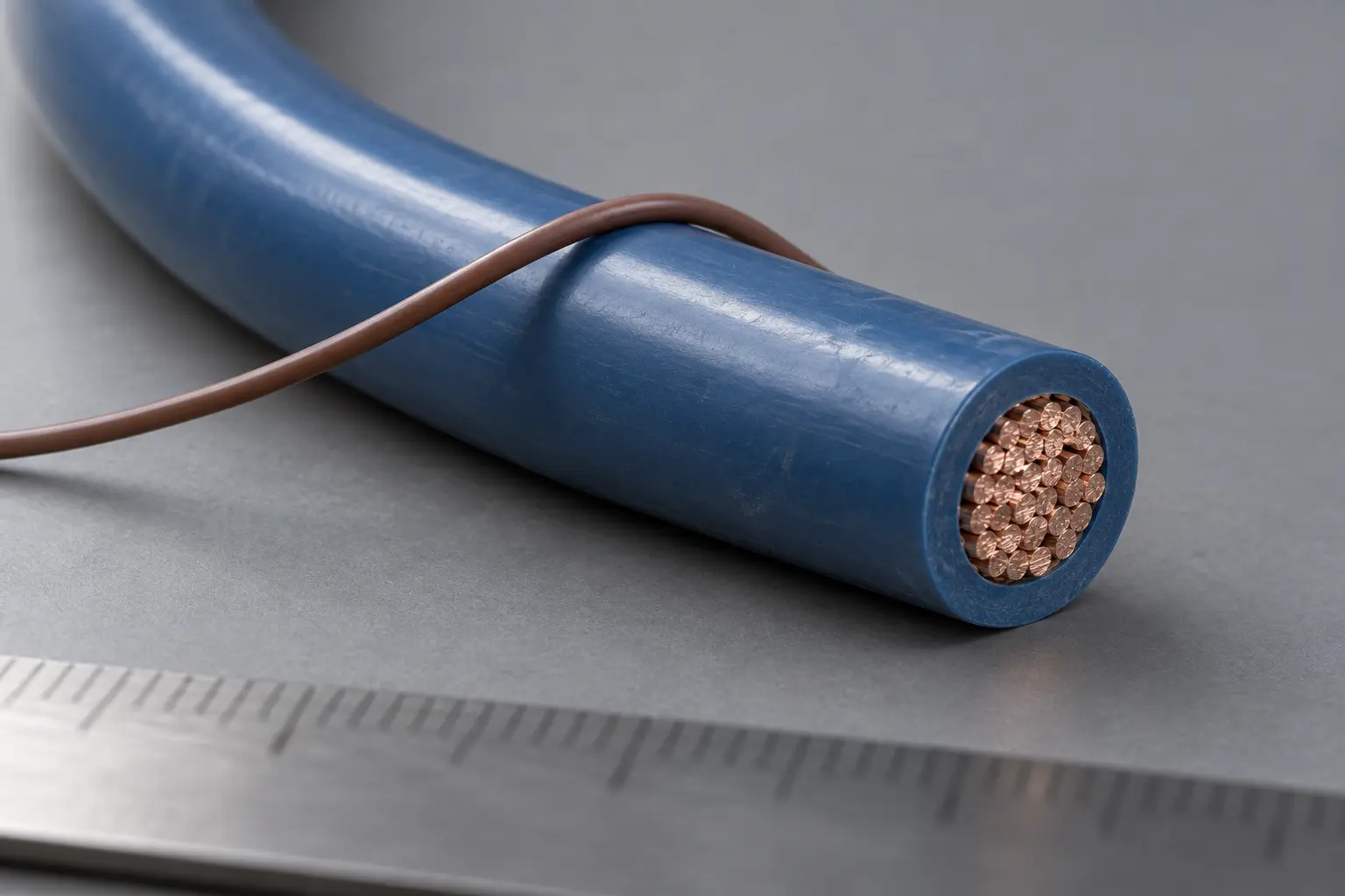
UL AWM Style 1015 is a single conductor with extruded PVC insulation, offering 80°C, 90°C or 105°C temperature rating options and 600 Vac or 750 Vdc voltage rating options, with Horizontal Flame. The full Style conductor range is 30 AWG through 2000 kcmil, solid or stranded.
This page covers two specific conductor sizes within that Style — 30 AWG and 8 AWG — for B2B procurement in the UAE and Saudi Arabia.
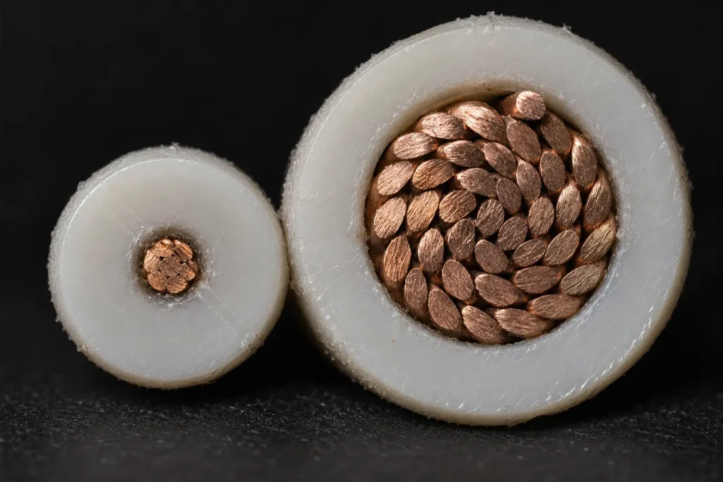
The two sizes are not variants of one construction. They fall into different Style insulation-wall groups, which is the substantive technical distinction this page exists to make clear. 30 AWG belongs to the 30–9 AWG group at 30 mils minimum average with 27 mils minimum at any point; 8 AWG belongs to the 8–7 AWG group at 45 mils minimum average with 40 mils minimum at any point.
The official Use is Internal Wiring of Appliances. Regional context does not modify it.
Verified UL Style 1015 Specification
| Parameter | Style-level information |
|---|---|
| UL AWM Style | 1015 |
| Product description | Single conductor with extruded insulation |
| Page-specific sizes | 30 AWG and 8 AWG |
| Temperature rating options | 80°C / 90°C / 105°C |
| Page-specific temperature sourcing focus | 105°C option where required |
| Voltage rating options | 600 Vac / 750 Vdc |
| Page-specific voltage sourcing focus | 600 Vac option where required |
| Flame | Horizontal Flame |
| Optional oil rating | 60°C or 80°C Oil |
| Full Style conductor range | 30 AWG–2000 kcmil |
| Conductor form | Solid or Stranded |
| Insulation | Extruded PVC |
| 30 AWG applicable insulation group | 30–9 AWG: 30 mil minimum average / 27 mil minimum at any point |
| 8 AWG applicable insulation group | 8–7 AWG: 45 mil minimum average / 40 mil minimum at any point |
| 6–2 AWG | 60 mil minimum average / 54 mil minimum at any point |
| 1–4/0 AWG | 80 mil minimum average / 72 mil minimum at any point |
| 250–500 kcmil | 95 mil minimum average / 86 mil minimum at any point |
| 550–1000 kcmil | 110 mil minimum average / 99 mil minimum at any point |
| 1100–2000 kcmil | 125 mil minimum average / 112 mil minimum at any point |
| Marking | General |
| Official Use | Internal Wiring of Appliances |
| Optional tag | 2,500 V peak – for electronic use only |
Seven clarifications belong with that table. 30 AWG and 8 AWG are the page-specific procurement sizes. They fall into different insulation-wall groups. 30/27 mil applies to 30 AWG. 45/40 mil applies to 8 AWG. 105°C and 600 Vac are page-level sourcing options rather than the only Style ratings. The full Style range does not equal inventory. And conductor material, detailed stranding, resistance, finished OD and ampacity all require separate confirmation.

Two Sizes, Two Insulation Groups
This is the strongest valid technical distinction between the two sizes on this page.
The Style insulation requirement is size-dependent. 30 AWG sits at the fine end of the broad 30–9 AWG group, which carries 30 mils minimum average with 27 mils minimum at any point. 8 AWG sits in the narrow 8–7 AWG group — only two conductor sizes wide — which carries 45 mils minimum average with 40 mils minimum at any point.
In each group the two figures are separate requirements, not a range. The first governs the average across the wall; the second sets a floor at every individual point on it. Neither is a nominal value, and neither is exact.
What this difference does not establish is equally important. It is not a signal-versus-power distinction, not light-duty versus heavy-duty, not low-current versus high-current, and not low-voltage versus high-voltage. Both remain Style 1015 constructions subject to the buyer’s actual design requirements.
AWG Is a Conductor Size, Not an Application Label
Conductor size alone does not establish signal use, power use, ampacity, circuit type or equipment function.
So this page refers to a 30 AWG Style 1015 construction and an 8 AWG Style 1015 construction — two size-specific procurement requirements — rather than assigning each a role. The customer drawing or bill of materials determines the circuit function, and the equipment design determines whether either size is appropriate.
Buyers may request one size or both. Nothing here implies the two must be purchased together, and no combined-order arrangement is guaranteed.
No Ampacity Is Published
UL AWM Style 1015 Product iQ does not provide one universal ampacity table, and no current rating is published here for either size.
Ampacity depends on the equipment design and its conditions — the conductor construction, the ambient temperature, bundling, the installation, the thermal environment and the applicable engineering standard. None of those is settled by a Style number or by an AWG figure.
No current value is therefore assigned to 30 AWG or to 8 AWG, and no signal-current or power-current capability is inferred from either size.
Metric Cross-Section, Finished OD and Resistance
Generic AWG-to-metric conversion data is not presented here as a verified SKU parameter. This page states 30 AWG and 8 AWG. Where a buyer requires a controlled metric conductor cross-section — common in UAE and Saudi procurement documents — request it and confirm the proposed conductor construction.
No finished outside diameter is published for either size. Style 1015 provides insulation-wall minimums, not one universal finished OD, and no diameter is derived from generic AWG dimensions plus a minimum wall. Actual OD depends on the conductor material, the solid or stranded construction, the strand geometry, the actual conductor diameter, the PVC extrusion and manufacturing tolerance.
No conductor resistance value is published either. The Style defines neither a universal conductor material nor a detailed conductor construction, so one universal resistance figure cannot exist, and generic copper AWG resistance tables are not copied in as product data.
Where these are controlled, state the maximum finished OD, the OD tolerance, the routing clearance, the terminal or connector entry, and the maximum conductor resistance in the RFQ so they can be verified against the proposed qualified construction.
Conductor Material, Plating and Stranding
The Style establishes the conductor size range and the solid or stranded form. It establishes nothing else about the conductor.
Copper, bare copper, tinned copper, silver-plated copper and nickel-plated copper are none of them universally defined by Style 1015, and no strand count, strand diameter or lay length is stated here. This page does not describe 30 AWG as tinned copper, does not describe 8 AWG as bare copper, and does not state that all Style 1015 is copper.
Conductor material, conductor finish or plating, the solid or stranded requirement and detailed strand construction are RFQ confirmation fields. The Style is also not characterised as fine-stranded, high-flex, extra-flexible or to any strand class.
Temperature and Voltage Options
Style 1015 provides 80°C, 90°C or 105°C temperature rating options. This page may be quoted for a 105°C Style 1015 construction where required. Style 1015 also provides 80°C and 90°C rating options, and the applicable rating must be confirmed for the ordered construction.
105°C is not the only Style rating, no single construction carries all three simultaneously, and no continuity qualifier is used — 105°C continuous and continuous 105°C operation do not appear here, because the Style record states the three options and nothing further.
The Style similarly provides 600 Vac or 750 Vdc voltage rating options. This page may be quoted for the 600 Vac option where required. The two are kept distinct: 750 Vdc is not restated as 750 Vac, and the pair is not merged into 600V AC/DC or a combined 600/750V designation. Which option applies to a given construction is confirmed rather than assumed.
The Optional Oil Rating and the 2,500 V Peak Tag
Style 1015 permits an optional 60°C or 80°C Oil rating. Style 1015 is not universally oil resistant, and no oil resistance at 105°C is implied. Where oil resistance is required, the applicable optional rating is specified and confirmed for the ordered construction.
The Style separately permits a tag indicating 2,500 V peak – for electronic use only. That is not the normal Style working-voltage rating. It is not written as 2500V rated, 2.5 kV wire, 2500 Vac or a 2500V working voltage, and both “peak” and “for electronic use only” stay attached wherever it is mentioned.
Horizontal Flame
The verified Style flame designation is Horizontal Flame. VW-1, FT1, vertical flame, flameproof and fire-resistant characterisations are not claimed here, and any additional flame requirement depends on separate confirmation for the ordered construction.
Internal Wiring of Appliances Is the Use
The formal UL Use is Internal Wiring of Appliances, and that wording is used exactly.
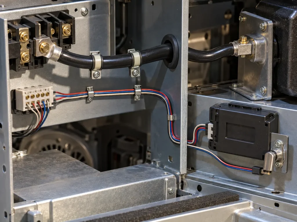
It is not broadened here into building wiring, field wiring, branch circuits, power distribution, tray cable, conduit wiring, facility wiring, electrical-room distribution or external equipment wiring. Neither the 600 Vac option nor the 8 AWG conductor size expands it — an AWM internal wire is not automatically a facility feeder, a building conductor or a branch-circuit cable.
Temperature and voltage ratings also do not establish suitability for an entire equipment sector, for a particular circuit topology, or for any named three-phase system voltage. The equipment design and the applicable standards control the application.
A further boundary worth stating: an AWM Style recognition does not make finished equipment compliant with any other product safety standard. No finished-equipment certification claim is made here.
Where a specific appliance or OEM product drawing requires Style 1015 as internal wiring, that requirement is reviewed according to that specification.
Full Style Range Is Technical Reference, Not Inventory
The complete Style range of 30 AWG through 2000 kcmil, and the full insulation-wall table above, appear for technical accuracy.
They do not indicate that every size is automatically in stock, regularly produced, available in every rating option, available in every colour or available at one order quantity. The commercial identity of this page remains 30 AWG and 8 AWG, and availability of a requested size and construction is confirmed per RFQ.
UAE and Saudi Arabia Sourcing
The buyer contexts this page addresses are UAE buyers requesting 30 AWG Style 1015, Saudi buyers requesting 8 AWG Style 1015, buyers sourcing both sizes under one technical enquiry, and OEM procurement requiring one of these sizes.
Geography here is commercial sourcing context. No named end users, project usage, approved-vendor status, national programme qualification or market-investment context is claimed, and no regulatory approval is implied by the destination.
What the destination affects is the commercial side of the enquiry: the quantity for each size, the packaging, the destination city or port, the Incoterm and the documentation the buyer needs.
Commercial Terms and Documentation
No minimum order quantity, sample quantity, combined-size order policy, stock position, lead time, transit time, freight-mode guarantee, production capacity, quotation response time, fixed Incoterm or fixed port is published here, and no manufacturing or quality-control procedures are described.
Required shipment documentation should be specified by the buyer and confirmed per order. Applicable RoHS / REACH documentation can be confirmed according to the ordered construction. Colour is treated the same way and is an RFQ field.
Bulk Wire and Processed Leads
This page primarily represents UL AWM Style 1015 single-conductor wire.
Nothing here implies that supply automatically includes cutting, stripping, crimping, terminals, connectors, finished leads or complete harnesses. Processed-wire requirements are separately specified and confirmed.
What Style 1015 Does and Does Not Define
The Style does define: 80, 90 or 105°C options; 600 Vac or 750 Vdc options; Horizontal Flame; an optional 60°C or 80°C Oil rating; 30 AWG–2000 kcmil; solid or stranded; extruded PVC; size-dependent insulation-wall requirements; the Use, Internal Wiring of Appliances; and the optional 2,500 V peak – for electronic use only tag.
The Style does not define:
- Conductor material, conductor plating, strand count, strand diameter and lay length
- A metric conductor cross-section for 30 AWG or 8 AWG
- Conductor resistance
- Finished OD and OD tolerance
- Ampacity and current rating
- Signal-circuit or power-distribution suitability
- Suitability for any named equipment category
- Building-wire suitability
- Colour and reel length
- MOQ, stock, lead time, production capacity and shipping term
Each requires the customer specification, verified SKU documentation, the applicable qualified construction, or commercial confirmation.
Common Procurement Errors
- Assuming 30 AWG automatically means signal wire.
- Assuming 8 AWG automatically means a 40A power wire.
- Publishing generic 0.5A or 40A ampacity.
- Publishing generic AWG-to-mm² conversions as SKU specifications.
- Publishing 1.1 mm or 7.4 mm as a universal finished OD.
- Publishing generic AWG resistance values.
- Assuming 30 AWG is universally tinned copper.
- Omitting the 27 mil minimum-at-any-point value for 30 AWG.
- Omitting the 40 mil minimum-at-any-point value for 8 AWG.
- Treating 105°C as the only Style temperature rating.
- Writing 105°C continuous.
- Combining 600 Vac and 750 Vdc into a 600/750V AC/DC rating.
- Using the 2,500 V peak tag as a normal voltage rating.
- Treating the optional Oil rating as universal.
- Turning Internal Wiring of Appliances into facility or distribution wiring.
- Assuming the full Style range means every size is stocked.
UAE and Saudi Arabia RFQ Checklist
- UL AWM Style 1015 requirement
- Required size: 30 AWG, 8 AWG or both
- Required temperature rating: 80°C, 90°C or 105°C
- Required voltage option: 600 Vac or 750 Vdc
- Whether the optional Oil rating is required
- Solid or stranded requirement
- Required conductor material
- Required conductor finish or plating
- Detailed strand construction, if controlled
- Exact appliance internal-wiring location
- Customer drawing
- Existing wire specification or bill of materials
- Maximum conductor resistance, if controlled
- Maximum finished OD, if controlled
- OD tolerance
- Colour
- Bulk wire or processed lead requirement
- Quantity for each AWG
- Packaging
- UAE or Saudi Arabia destination
- Destination city or port
- Requested Incoterm
- Required compliance or shipping documentation
None of these values is invented here, and no requested configuration is presented as automatically available.
UL Marking and Documentation
Material is supplied as UL-recognized component wire where supplied under qualified manufacturing scope, and UL marking is applied according to the confirmed ordered construction. The Style-level marking designation is General.
CSA AWM, FT1, VW-1 and dual UL / CSA certification are not claimed here; any additional certification depends on the ordered construction. Applicable RoHS / REACH documentation can be confirmed according to the ordered construction.