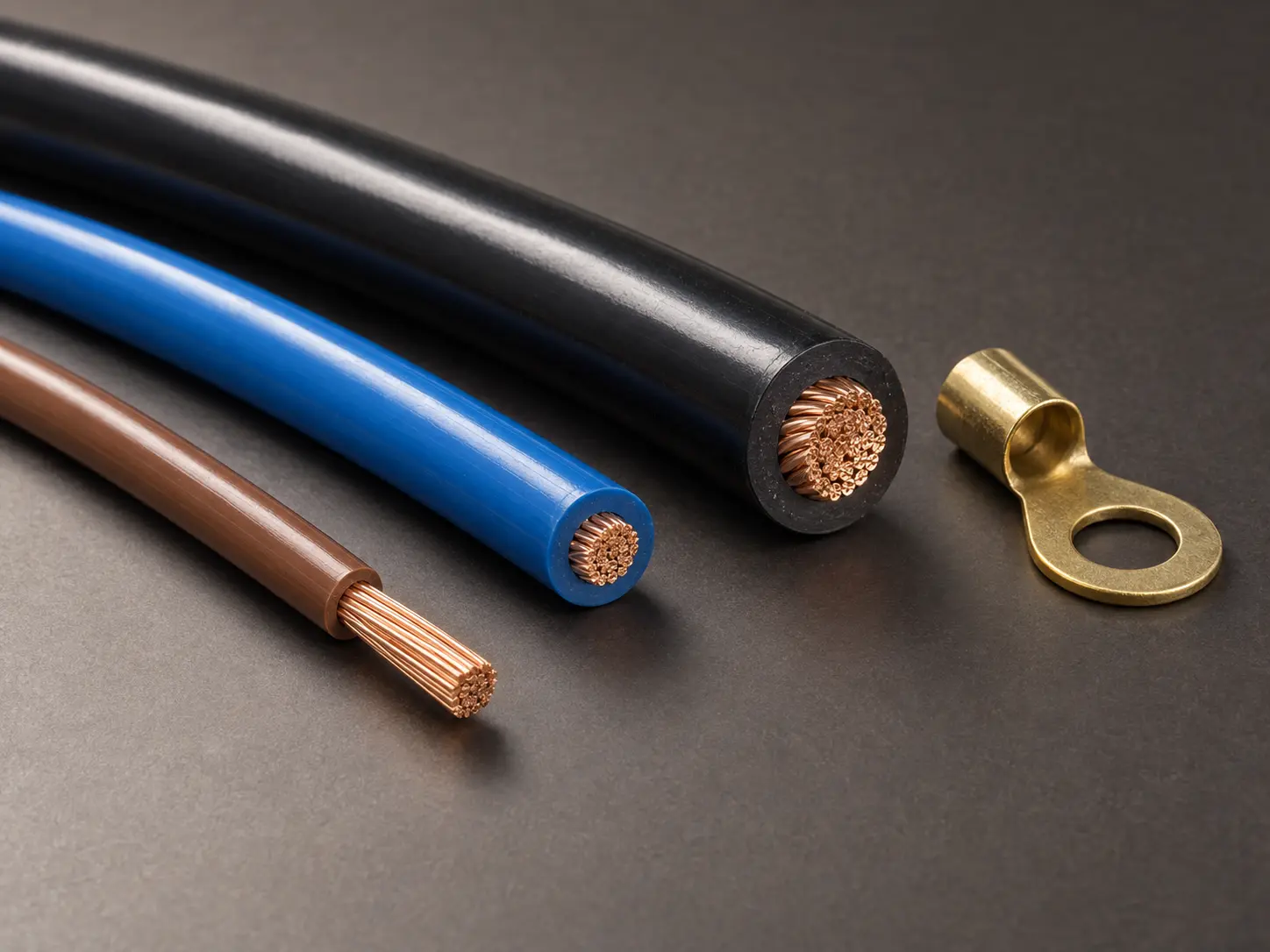
UL 1015 for Internal Leads in Appliance Power Sections
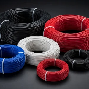
UL AWM Style 1015 is a single conductor with extruded PVC insulation, with 80°C, 90°C or 105°C rating options, voltage ratings of 600 Vac or 750 Vdc, and a Horizontal Flame designation. The conductor range is 30 AWG through 2000 kcmil, solid or stranded.
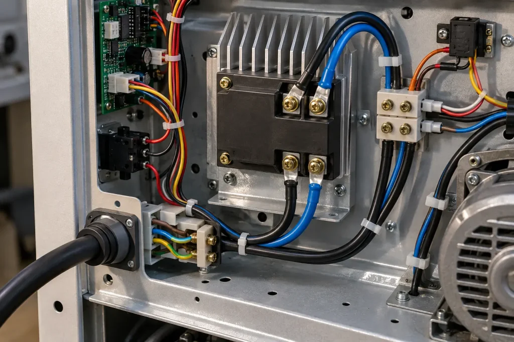
This page covers that wire as fixed internal leads associated with an appliance’s internal power section or power module. The official Use is internal wiring of appliances, and every application statement here stays inside it.
Power supply lead wire is this page’s commercial positioning, not UL wording. On this page it means fixed internal wiring associated with an appliance’s internal power section, power conversion module or power-related internal components. UL Product iQ does not identify power supply lead wire as the Style 1015 Use, and Style 1015 is not a dedicated power-supply wire standard.
Verified UL Style 1015 Specification
| Parameter | Style-level information |
|---|---|
| UL AWM Style | 1015 |
| Construction | Single conductor with extruded insulation |
| Temperature rating | 80°C, 90°C or 105°C |
| Voltage rating | 600 Vac or 750 Vdc |
| Flame | Horizontal Flame |
| Optional oil rating | 60°C or 80°C Oil |
| Conductor range | 30 AWG–2000 kcmil |
| Conductor form | Solid or Stranded |
| Insulation | Extruded PVC |
| 30–9 AWG | 30 mil average / 27 mil minimum |
| 8–7 AWG | 45 mil average / 40 mil minimum |
| 6–2 AWG | 60 mil average / 54 mil minimum |
| 1–4/0 AWG | 80 mil average / 72 mil minimum |
| 250–500 kcmil | 95 mil average / 86 mil minimum |
| 550–1000 kcmil | 110 mil average / 99 mil minimum |
| 1100–2000 kcmil | 125 mil average / 112 mil minimum |
| Marking | General |
| Official Use | Internal Wiring of Appliances |
| Optional tag — not a voltage rating | 2,500 V peak – for electronic use only |
Three points follow from the table. The power-supply positioning of this page refers only to appliance internal power sections. The full Style range describes permitted construction scope and does not equal guaranteed stock. And the optional 2,500 V peak tag is separate from the normal voltage rating.
Circuit Function Does Not Change the Voltage Rating
This is the most useful thing to establish on a page about power-section leads.
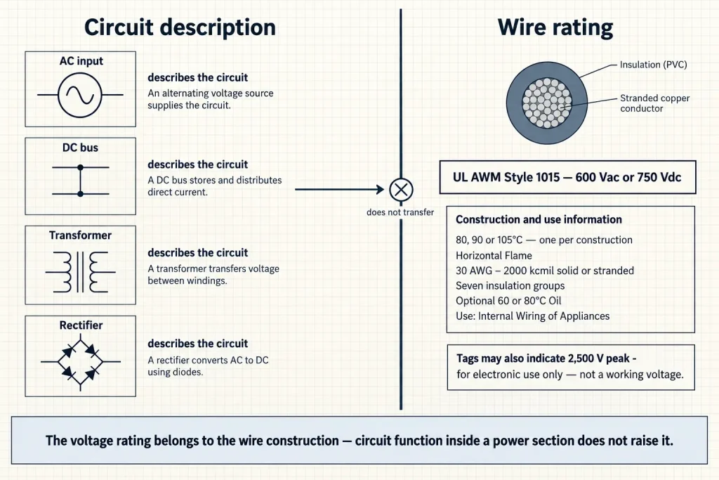
Style 1015 is rated 600 Vac or 750 Vdc. That rating is a property of the wire construction, and it does not increase because the wire is installed in a power section. Circuit-output voltage, DC bus voltage and power-converter terminology describe the circuit, not the wire, and none of them confers additional wire rating.
Where a circuit condition exceeds what the Style provides, the answer is a different construction or a different Style, arrived at from the appliance specification.
The two ratings are also kept distinct here. 750 Vdc is not written as 750 Vac, 600/750 Vac, 600V AC/DC or 750V AC/DC. Where commercial text uses the shorthand 600V, the technical position remains 600 Vac or 750 Vdc, and the enquiry should state which condition applies at the lead position.
Internal Power Wiring Is Not External Power Wiring
An appliance’s internal power section and the cable that supplies the appliance are different product categories.
Style 1015 is not an external appliance power cord, a mains cord, a line cord, a portable cord, an extension cord or a building supply cable. The Use is internal wiring of appliances, and that boundary does not move because the lead carries the power circuit.
Where the power-entry area is being discussed, Style 1015 belongs to the internal connection architecture — after or within it — and not as the building-to-appliance supply cable, a detachable mains cord or a field-installed branch-circuit conductor.
The Use also does not extend to standalone industrial power supplies, power distribution units, control cabinets, switchboards, inverters, UPS systems, server power supplies, industrial electrical equipment, building wiring, field wiring, branch circuits, tray, conduit or raceway.
Appliance Power-Section Contexts
The buyer contexts this page addresses are internal leads between an appliance power module and other internal components, fixed leads associated with appliance power-input sections after the external cord or inlet interface, internal power-distribution leads located inside an appliance, component-to-component wiring within an appliance power section, and drawing-controlled appliance power-module leads.
These are page-level commercial contexts. UL does not separately approve any architecture or appliance type through this Style, and no such approval is implied.
Temperature Rating Is Selected, Not Assumed
Style 1015 includes 80°C, 90°C and 105°C rating options; the applicable rating must be confirmed for the ordered construction. No ordered wire simultaneously carries all three.
A power section is not automatically a reason to require 105°C. Whether a higher rating is needed depends on the temperature at the lead’s actual installed position, and that is an appliance design output rather than an inference from the circuit function.
No thermal derating, temperature rise, distance from a transformer, distance from a heat sink or maximum internal ambient figure is published here. Where the wire location is thermally significant, state the expected temperature at that location in the enquiry.
The 2,500 V Peak Tag
Style 1015 permits an optional tag stating 2,500 V peak – for electronic use only. This is not the ordinary Style working voltage.
Normal Style rating: 600 Vac or 750 Vdc.
Optional tag: 2,500 V peak – for electronic use only.
It is not written here as 2500V power supply wire, a 2.5 kV power lead, 2500 Vac, 2500 Vdc, 2.5 kV continuous or 600/2500V, and it is not presented as a commercial feature of this page.
Conductor Size Is Not Set by the Circuit Description
No AWG is chosen or recommended here on the basis that a circuit is described as a power circuit. Wire size depends on the complete appliance design.
No current capacity, ampacity, heater current, motor current, power rating or wattage is published, and no statement is made that a particular AWG suits a particular current. A universal Style 1015 ampacity table does not exist, ampacity is not calculated from AWG alone, and no maximum amps, continuous amps or recommended current figure appears on this page. These belong to the complete appliance design.
Suitability for AC input, DC output, high-current output, a transformer primary, a transformer secondary, a DC bus, a battery input or a rectifier output is likewise not claimed. Where a customer identifies one of those circuit functions, it is evaluated from the actual appliance specification rather than treated as a universal Style application.
Seven Insulation Groups
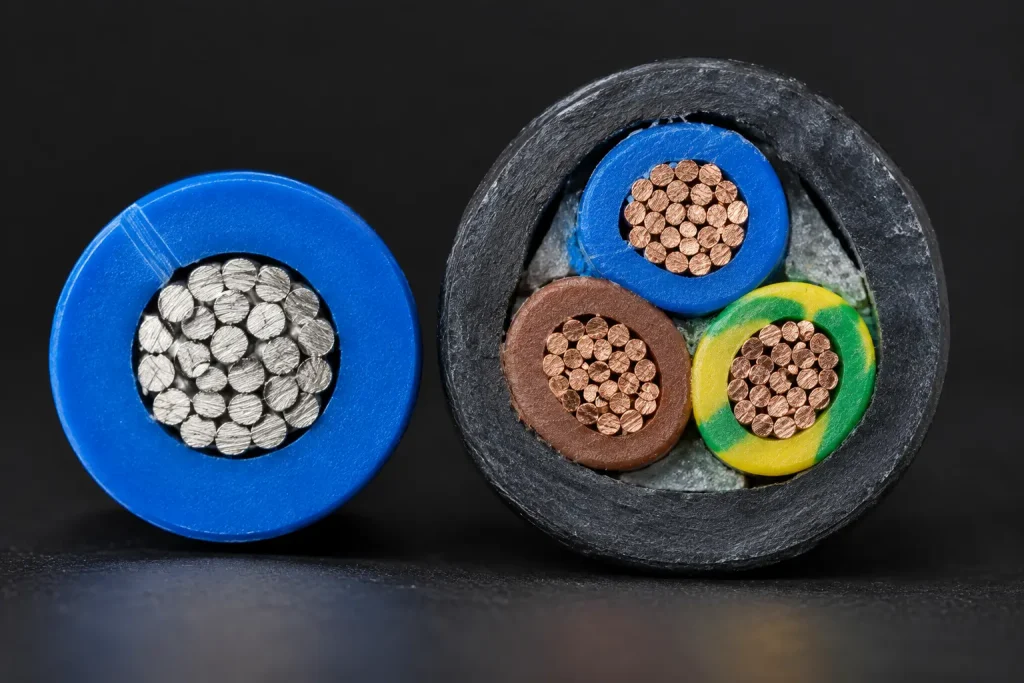
Style 1015 defines seven insulation groups across its conductor range, each with a minimum average thickness and a separate minimum thickness at any point. These are not nominal thicknesses, and Style 1015 is not reduced here to one universal insulation wall.
Power-section work frequently involves a heavier conductor than the surrounding control wiring, which makes the group boundaries relevant: a supply lead and a control lead in the same appliance can sit in different groups and therefore describe different constructions under one Style number.
Conductor Material and Form
Style 1015 does not universally define copper, bare copper, tinned copper, silver-plated copper or nickel-plated copper, and it defines no strand count, strand diameter, lay length or conductor resistance.
Where a customer requires tinned copper, bare copper, a particular strand count or a specific conductor diameter, each is an order-specific RFQ requirement supported by the applicable qualified construction or verified SKU data.
Both solid and stranded are permitted, so Style 1015 is not described here as universally stranded, and the wire is not called flexible, high-flex or extra-flexible — the supplied Style data establishes no flex class or flex-cycle rating.
Style Range and Commercial Availability
The Product iQ range of 30 AWG through 2000 kcmil describes permitted Style construction scope. It does not prove inventory, standard stock sizes, routine production of every size, MOQ or lead time.
Commercial availability of any particular size and construction combination is confirmed for the ordered construction.
Termination
Style 1015 establishes no terminal compatibility, crimp performance, solderability, connector compatibility, strip force or termination retention, and no claim about ease of termination is made here.
Where termination is controlled by the appliance design, supply the terminal, the connector, the strip length, the conductor finish and the conductor dimensions as relevant. Those requirements come from the drawing; none is inferred from the Style.
Finished OD
Style 1015 establishes no universal finished outside diameter, and no guaranteed OD is calculated here from gauge plus minimum insulation wall.
Actual OD depends on the conductor size, the solid or stranded construction, the actual conductor diameter, the actual extrusion and manufacturing tolerance. Where appliance power-module routing is dimension-controlled, specify the maximum OD, the OD tolerance, the routing clearance and the terminal-entry requirements. No standard OD value is published.
Optional Oil Rating
Style 1015 includes an optional 60°C or 80°C Oil rating. Not all Style 1015 wire is oil resistant.
For appliances where oil exposure is relevant at the lead position, ask whether the applicable optional Oil rating is required and confirm it for the ordered construction. The optional rating is not broadened here into generic chemical resistance.
Horizontal Flame
The verified Style designation is Horizontal Flame. VW-1, FT1 and vertical flame are not claimed here, and any separately confirmed flame requirement remains construction-specific.
Bulk Wire and a Processed Power Lead
This page primarily represents Style 1015 single-conductor wire.
Nothing here implies that a quotation includes cut leads, stripping, terminals, crimps, connectors or complete power harnesses. Where processed leads are required, those requirements are separately specified and confirmed, and saying which is needed in the first enquiry avoids quoting the wrong scope.
Repeat Appliance Programs
Repeat OEM purchasing is a legitimate procurement context, and no supply promise is attached to it here: no stable supply, repeatability, batch consistency, inventory, fixed lead time, colour consistency or production capacity is guaranteed.
What holds a repeat program steady is controlling the specification — the Style, the AWG, the conductor construction, the temperature rating, the voltage requirement, the insulation construction, the dimensions, the colour, the marking, the packaging, and the approved specification or drawing where one exists.
What Style 1015 Does Not Define
- Conductor material, plating, strand count, strand diameter and lay length
- Conductor resistance, ampacity, current rating, power rating and wattage
- Finished OD and OD tolerance
- Bend radius and flex life
- Terminal, connector, cut length and colour
- MOQ, stock, lead time and production capacity
Each requires the customer specification, verified SKU documentation, the applicable qualified construction, or commercial confirmation.
Common Procurement Errors
- Every Style 1015 wire assumed to be 105°C. 80°C and 90°C are equally Style options.
- The 750 Vdc rating omitted. Both voltage ratings belong in the specification.
- 2,500 V peak treated as an ordinary 2.5 kV working voltage.
- Tinned stranded copper assumed. Conductor material is not set at Style level.
- One insulation thickness used across the full Style range. Seven groups apply.
- Power-supply use assumed to provide a higher voltage rating. The rating belongs to the wire.
- Ampacity published from AWG alone.
- A power module assumed to determine one standard AWG.
- Style 1015 assumed to include terminals or processed leads.
- All Style 1015 assumed oil resistant. The Oil rating is optional.
- Used for external mains cords. The Use is internal wiring.
- Used for field-installed or building power wiring.
- Standalone industrial power supplies treated as within the official Use.
Power-Section RFQ Checklist
- UL AWM Style 1015 requirement
- Appliance type
- Location of the lead inside the appliance
- Power-module or internal power-section function
- Required AWG or kcmil size
- Solid or stranded conductor
- Required conductor material
- Required conductor plating or finish
- Strand construction, if controlled
- Required temperature rating: 80°C, 90°C or 105°C
- 600 Vac or 750 Vdc requirement
- Optional Oil rating, if required
- Expected wire-location temperature, if relevant
- Maximum finished OD, if controlled, and OD tolerance
- Insulation colour
- Terminal or connector interface
- Strip or termination requirements, if a processed lead is required
- Wire length, if cut leads are requested
- Marking
- Customer drawing or existing wire specification
- Quantity, packaging and destination
- Required compliance documentation
None of these values is invented here, and no requested construction is presented as automatically available.
Style Selection
Each AWM Style is evaluated according to its official Use, temperature, voltage, construction, conductor range and the customer specification. XLPE, silicone and fluoropolymer constructions are not described here as automatically more appropriate because a different polymer is wanted, and this page is not an insulation-material comparison.
UL Marking and Documentation
Material is supplied as UL-recognized component wire where supplied under qualified manufacturing scope, and UL marking is applied according to the confirmed ordered construction. The Style-level marking designation is General.
CSA AWM, FT1, VW-1 and dual UL / CSA certification are not claimed here; any additional certification depends on the ordered construction. Applicable RoHS / REACH documentation can be confirmed according to the ordered construction.