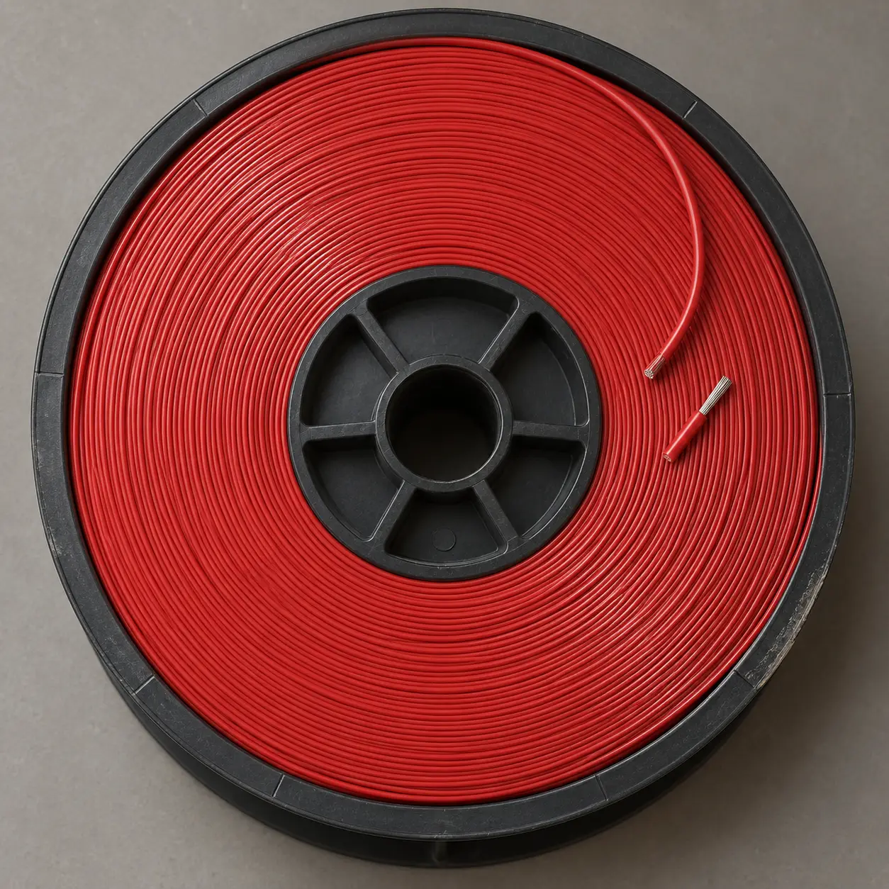
UL 1569 for Fixed Internal Wiring of Appliances
UL AWM Style 1569 is a single conductor with extruded PVC insulation, rated 300 Vac with Horizontal Flame, in 80°C, 90°C or 105°C temperature ratings. The Style conductor range is 30 AWG through 2 AWG, solid or stranded.
This page covers the appliance branch of that Style, with commercial emphasis on the 30–10 AWG group, where the base insulation requirement is 15 mils minimum average with 13 mils minimum at any point.
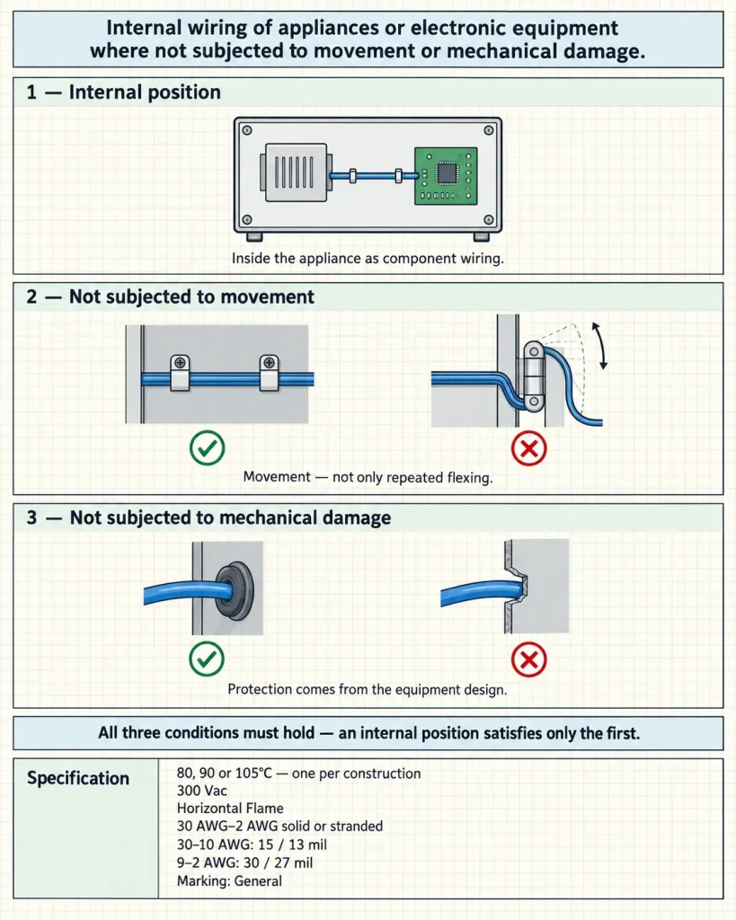
The official Use reads: internal wiring of appliances or electronic equipment where not subjected to movement or mechanical damage. That single sentence carries three conditions, and all three have to hold — the section below sets them out, because the second and third are the ones most often lost when the Use is quoted in shortened form.
Verified UL Style 1569 Construction
| Parameter | Style-level information |
|---|---|
| UL AWM Style | 1569 |
| Construction | Single conductor with extruded insulation |
| Temperature | 80°C, 90°C or 105°C |
| Voltage | 300 Vac |
| Flame | Horizontal Flame |
| Conductor range | 30 AWG–2 AWG |
| Conductor form | Solid or Stranded |
| Insulation | Extruded PVC |
| 30–10 AWG insulation | 15 mil average / 13 mil minimum at any point |
| 9–2 AWG insulation | 30 mil average / 27 mil minimum at any point |
| Optional covering | Extruded PVC, 9 mil average / 8 mil minimum at any point |
| Marking | General |
| Official Use | Internal wiring of appliances or electronic equipment where not subjected to movement or mechanical damage |
| Optional tag — not a normal rating | 600 Volts Peak for Electronic Use Only |
This page commercially focuses on the 30–10 AWG / 15 mil group for fixed appliance internal wiring.
Three Conditions in One Sentence
The Use is frequently shortened in specifications to “internal wiring of appliances,” which drops two thirds of what it says.
First, the wiring is internal. The wire sits inside the appliance as component wiring, not as anything installed to the appliance or around it.
Second, it is not subjected to movement. Note the wording — movement, not merely repeated flexing. An internal lead that travels with a moving part is outside the Use even if it moves slowly and rarely.
Third, it is not subjected to mechanical damage. This places a protection obligation on the appliance design, separate from the movement condition.
All three must hold. An internal position satisfies the first condition only, and the other two are evaluated against the actual routing and the actual appliance mechanism. Confirming them in the enquiry is more useful than describing the appliance category.
Fixed Internal Wiring, Not Moving Wiring
Appliances contain moving parts by definition, and internal wiring near them is common.
Style 1569 is not recommended here for door-hinge wiring, sliding mechanisms, repeated-flex loops, moving appliance mechanisms, robotic applications, drag chains or continuous-flex harnesses. Where part of a run travels with a lid, drawer, arm or carriage, that section falls outside the Use even where the rest of the run is stationary and correctly specified.
No flex-cycle performance, bend-life rating or dynamic classification is published here, because the Style record establishes none.
Mechanical Protection Is a Design Obligation
The third condition is met by the appliance design rather than by the wire.
No special abrasion resistance, impact resistance, cut-through protection or mechanical reinforcement is claimed for Style 1569. Where the installed wire may be exposed to mechanical damage — a sheet-metal edge, a pinch point during assembly, a position reached during service — the equipment designer evaluates the actual protection arrangement or an alternative construction.
Describing the protection method in the enquiry (grommet, sleeve, clip with an insulating saddle, formed channel) helps establish that the condition is satisfied.
The 30–10 AWG Group and Its Verified Basis
The commercial focus of this page is the 30–10 AWG group, and the reason is a verified figure rather than a claim: the base PVC insulation requirement is 15 mils minimum average with 13 mils minimum at any point.
That figure is not turned into a guaranteed smaller OD, maximum space savings, easier assembly, cleaner routing, highest packing density, reduced appliance size or lighter product weight. It is an insulation-wall requirement.
What buyers working with dimensional constraints can do with it is evaluate this insulation-wall group against their required maximum finished OD and available routing space — an assessment made against the ordered construction, not against the Style figure alone.
Thin-Wall Describes One Group
Style 1569 has two base-insulation groups. 30–10 AWG requires 15 mils minimum average with 13 mils minimum at any point; 9–2 AWG requires 30 mils minimum average with 27 mils minimum at any point.
Thin-wall is used on this page for the first group only. It is not accurate to say all Style 1569 uses 15 mil insulation, that 30 AWG through 2 AWG share the same wall, or that Style 1569 officially means thin-wall wire. The Style extends through 2 AWG, and thin-wall is a commercial descriptor rather than the formal UL Style title.
Appliance Application Contexts
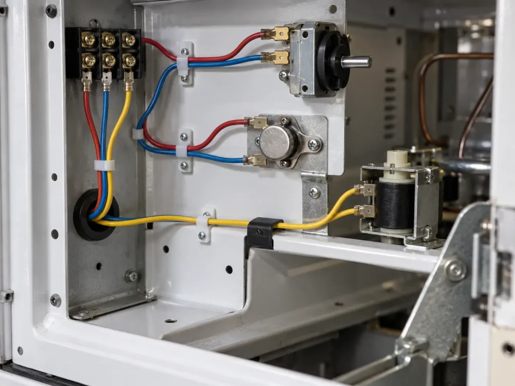
The contexts this page addresses are internal component-to-component appliance leads, fixed internal power or control leads, protected wiring between terminals, controls, switches, relays, sensors and other internal appliance components, drawing-controlled appliance internal wiring, and stationary appliance lead routing.
These are application contexts under the official Use. UL has not separately approved any named appliance or component application through this Style, and no such approval is implied.
The Use also does not extend to building wiring, field wiring, branch-circuit wiring, tray wiring, conduit wiring, raceway, external appliance cords, portable cords, power supply cords or general field-installed equipment wiring. The cord that supplies an appliance and the wire inside it are different product categories.
Finished Outside Diameter
Style 1569 does not specify one universal finished OD, and none is invented here.
Actual finished OD depends on the AWG, the solid or stranded conductor form, the detailed conductor construction, the actual insulation extrusion, and whether the optional PVC covering is included. It is not calculated from the minimum insulation wall alone.
Where the appliance design controls wire dimensions, supply the maximum finished OD, the OD tolerance and the available routing clearance in the enquiry.
Temperature Rating
Style 1569 permits 80°C, 90°C or 105°C. These are alternatives; not every ordered wire carries all three.
Nothing here states that all Style 1569 is 105°C or that 105°C is the standard construction. The required temperature rating is confirmed for the selected ordered construction, and in an appliance with circuits in different thermal positions it may differ between wire schedule lines.
300 Vac and the Optional Peak Tag
The normal Style voltage rating is 300 Vac, used precisely here. The product is not described as 600V wire, 600 Vac wire or 300/600V wire.
Style 1569 may separately carry an optional tag indicating “600 Volts Peak for Electronic Use Only.” That is separate from the normal rating and is not converted into 600 Vac, 600V continuous, 600V appliance wire or 300/600V wire. On an appliance-focused page it is noted for completeness rather than developed, since the tag itself is scoped to electronic use.
The Optional PVC Covering
An optional extruded PVC covering is permitted at 9 mils minimum average with 8 mils minimum at any point.
Not every Style 1569 wire has it, and it is not called a jacket, double insulation, mechanical protection, abrasion protection or reinforcement here — none of those characteristics is established by the Style information. Where it is required, the buyer specifies it as part of the ordered construction.
Conductor Requirements
Style 1569 establishes the 30 AWG–2 AWG range and the solid or stranded form. It establishes nothing else about the conductor.
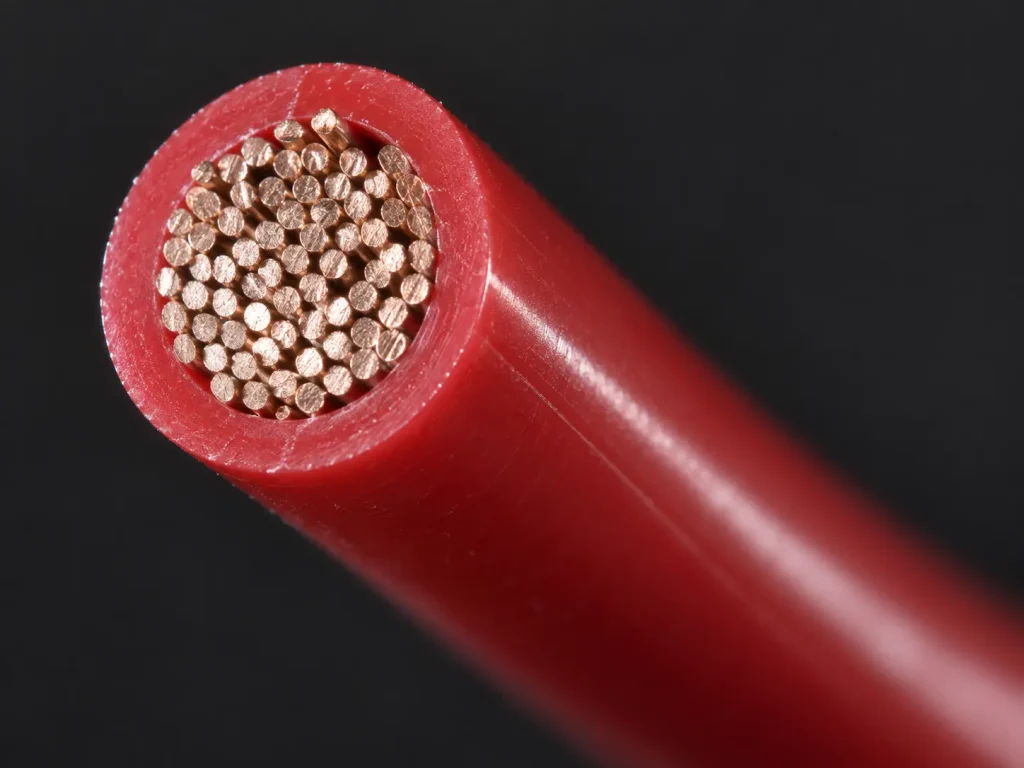
Copper, tinned copper, bare copper, silver-plated copper and nickel-plated copper are none of them established at Style level, and no strand count, strand diameter, lay length, conductor resistance or ampacity is stated. For RFQ purposes, conductor material, plating and detailed stranding are confirmed according to the ordered construction or verified SKU documentation.
No Universal Ampacity
No universal ampacity or current rating is published for Style 1569, and an AWG combined with a Style number does not establish one.
Actual current capability is an equipment-design matter affected by the conductor construction, the installation, the ambient conditions and the complete appliance design. It belongs to the appliance engineering rather than to the wire specification.
What UL Style 1569 Does Not Define
- Conductor material and conductor plating
- Strand count and strand diameter
- Finished OD and OD tolerance
- Conductor resistance, ampacity and current rating
- Bend radius and flex life
- Colour
- Terminal, connector and cut length
- MOQ, stock and lead time
Each must come from the buyer’s specification, verified SKU documentation or commercial confirmation.
Common Procurement Errors
- 15 mil insulation assumed for every size. It applies to 30–10 AWG only.
- Style 1569 described as universally thin-wall. The 9–2 AWG group requires 30 mil average.
- Every ordered wire assumed to carry 105°C. The Style permits 80, 90 or 105°C.
- 600 Volts Peak read as 600 Vac. The normal rating is 300 Vac.
- Stranded tinned copper assumed. Conductor material is not set at Style level.
- One universal finished OD assumed. OD depends on size, conductor form and covering.
- Selected for moving appliance wiring. The Use excludes movement.
- Mechanical-damage restriction ignored. It is a separate condition from movement.
- Optional PVC covering assumed always present.
- Wire selected from AWG alone. Conductor construction and dimensional requirements still need confirming.
Appliance RFQ Checklist
- UL AWM Style 1569 requirement
- Required AWG
- Whether the application falls within the 30–10 AWG thin-wall group
- Solid or stranded conductor
- Required conductor material
- Conductor finish or plating
- Stranding, if specified
- Required temperature rating: 80°C, 90°C or 105°C
- 300 Vac requirement
- Insulation colour
- Optional PVC covering, if required
- Maximum finished OD, if controlled
- OD tolerance
- Appliance type
- Fixed internal installation position
- Whether the wire will remain stationary
- Mechanical-protection conditions
- Terminal or connector requirements, if relevant
- Required markings
- Quantity, packaging and destination
- Required compliance documentation
These are buyer inputs. None is invented or assumed on the buyer’s behalf.
Selection Against Other AWM Styles
Different AWM Styles have independent construction requirements, Uses, temperature ratings, voltage ratings and insulation structures. None is presented here as a direct substitute for Style 1569 on the basis of voltage or apparent wire size.
Any alternative requires evaluation against the customer’s actual specification — including, on this Style, the movement and mechanical-damage conditions that other Styles may word differently or not carry at all.
UL Marking and Documentation
Material is supplied as UL-recognized component wire where supplied under qualified manufacturing scope, and UL marking is applied according to the confirmed ordered construction. The Style-level marking designation is General.
CSA AWM, FT1, VW-1 and dual UL / CSA certification are not claimed here; any additional certification depends on the ordered construction. Applicable RoHS / REACH documentation can be confirmed according to the ordered construction.
Flame Classification
The verified Style-level designation is Horizontal Flame. VW-1 and FT1 are separate classifications and are not claimed here; Horizontal Flame is not converted into either. Any separately confirmed vertical-flame requirement remains order-specific.