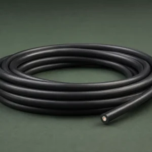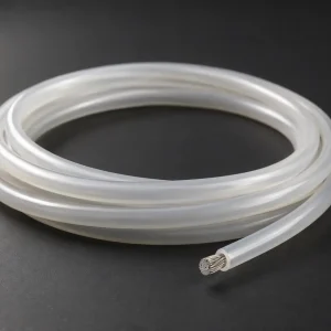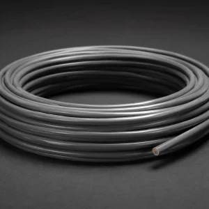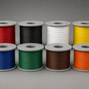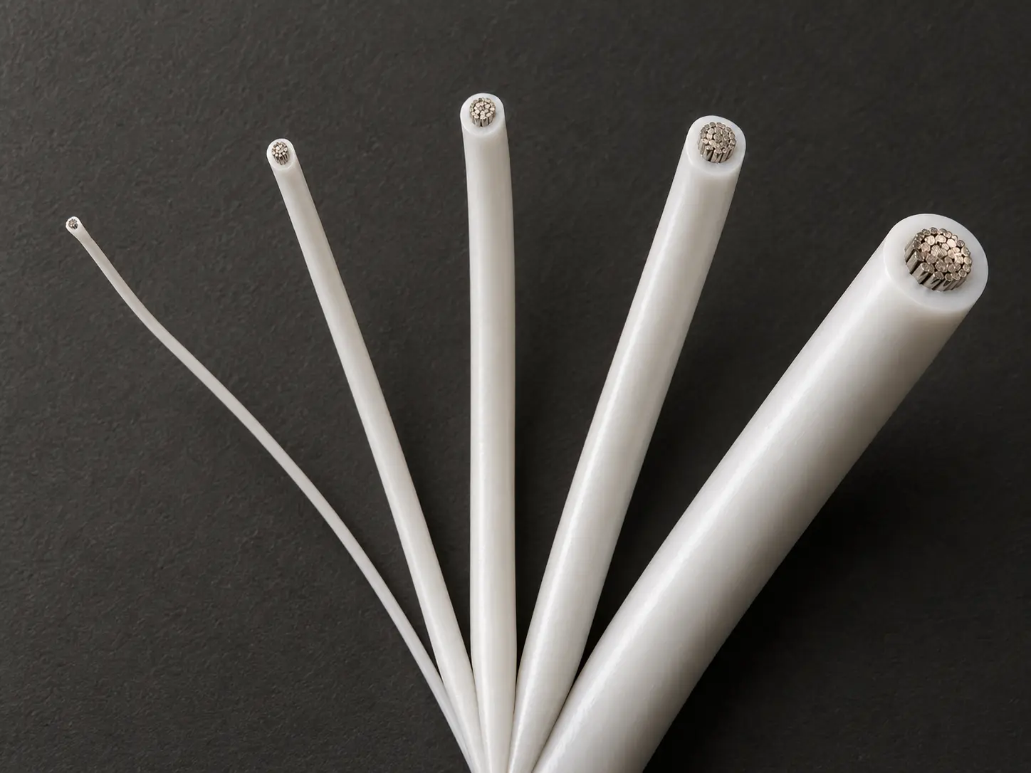
UL 1659 PTFE/TFE Wire for Thermal Equipment Internal Leads
UL AWM Style 1659 is a single conductor with extruded PTFE / TFE insulation, rated 250°C and 600 Vac with Horizontal Flame, across a 26 AWG through 4/0 AWG conductor range in solid or stranded round form.
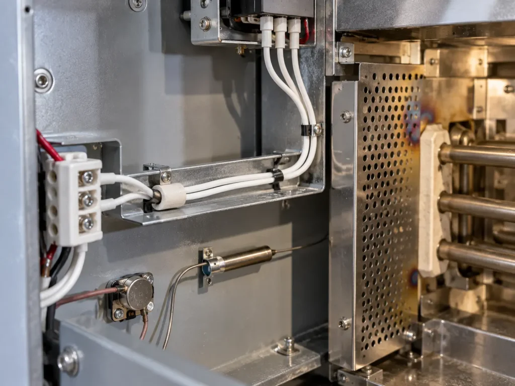
This page addresses internal leads inside thermal equipment and heat-influenced internal equipment sections, where a 250°C Style rating is specified by the equipment drawing. Thermal equipment is the commercial application context of this page; the formal Style Use remains internal wiring.
The whole conductor range is retained here rather than narrowed, because thermal equipment spans very different conductor sizes — a sensor lead and a heating-circuit lead in the same machine can sit at opposite ends of the Style.
Verified UL Style 1659 Specification
| Parameter | Style-level information |
|---|---|
| UL AWM Style | 1659 |
| Construction | Single conductor with extruded insulation |
| Temperature | 250°C |
| Voltage | 600 Vac |
| Flame | Horizontal Flame |
| Optional rating | Oil Res 80°C |
| Optional rating | Gasoline Resist |
| Conductor range | 26 AWG–4/0 AWG |
| Conductor form | Solid or Stranded Round |
| Insulation | PTFE / TFE |
| 26–10 AWG insulation | 20 mil average / 18 mil minimum |
| 8–2 AWG insulation | 30 mil average / 27 mil minimum |
| 1–4/0 AWG insulation | 45 mil average / 40 mil minimum |
| Optional covering | Mica tape wrap |
| Optional braid | Treated glass braid |
| Marking | General |
| Official Use | Internal wiring |
Thermal equipment is this page’s commercial application context. The formal Style Use remains internal wiring, and that boundary is not changed by the equipment category.
Note on the thickness table: the official groups run 26–10 AWG, then 8–2 AWG, then 1–4/0 AWG, with no 9 AWG row. Where 9 AWG is requested, the applicable qualified construction should be confirmed before quotation.
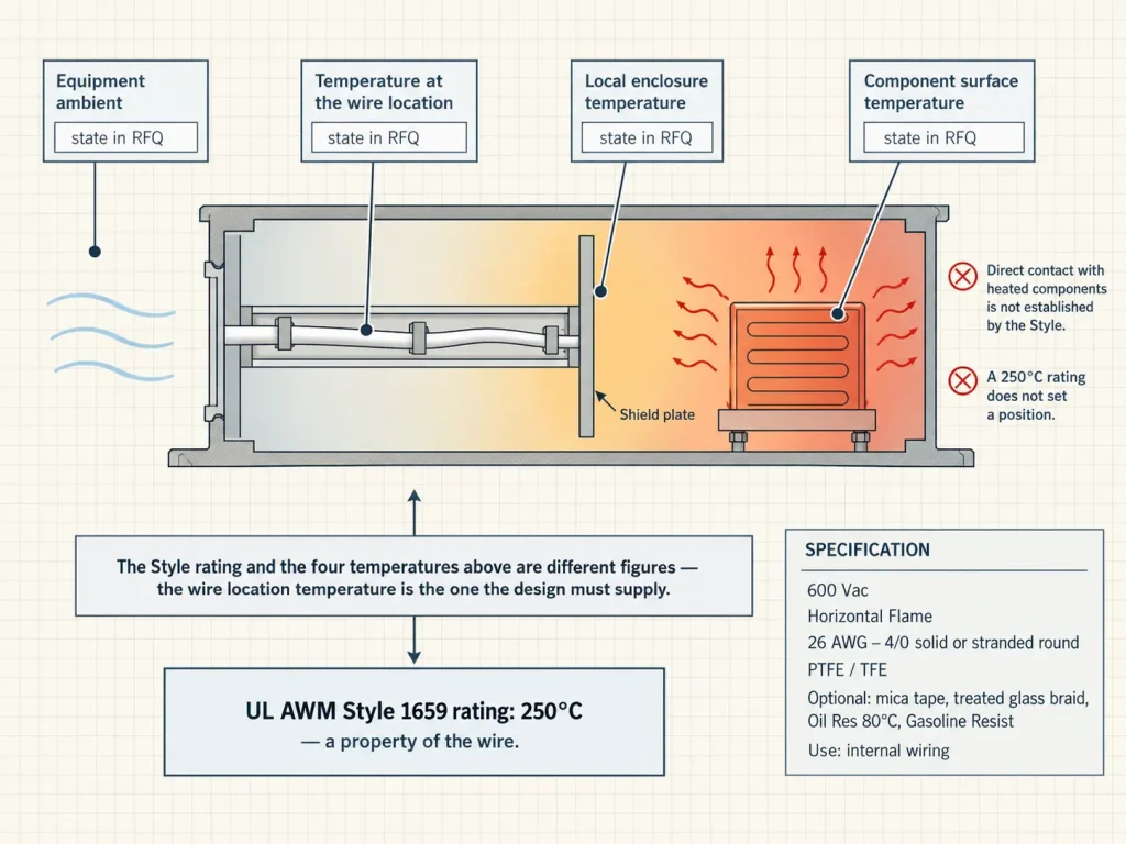
The Wire Rating and the Equipment Temperature Are Different Figures
This is the distinction that matters most when specifying a lead for thermal equipment, and it runs in both directions.
A 250°C wire rating does not mean the whole equipment operates at 250°C, that the wire must operate at exactly 250°C, that it may touch a 250°C heating element, that it can be placed in an open flame, or that it can be positioned anywhere in relation to a heat source. The rating describes the wire; the position describes the design.
Nor does producing heat make a product a Style 1659 application. Equipment designers evaluate the actual internal temperature, the voltage, the construction and the installation, and Style 1659 is appropriate where that evaluation says so rather than because the equipment is thermal.
Which Temperature to Specify
Thermal assemblies rarely have one temperature. Equipment ambient, local enclosure temperature, component-surface temperature and the temperature at the wire’s own installation position can differ substantially, and using “ambient” loosely obscures which one is meant.
For RFQ and design review, the useful figures are:
- Expected temperature at the wire location
- Normal operating temperature
- Possible maximum local temperature
- The distance or relationship to the heat source, where relevant
- Whether radiant heat is significant at that position
- Whether the wire touches heated metal or is routed separately
No numerical spacing requirement, derating curve or thermal calculation is offered here. Those belong to the equipment’s own thermal design, and the wire specification is checked against their output rather than substituting for them.
Contact With Heated Components
Nothing on this page states that Style 1659 may be installed directly against heating elements, heater coils, open resistance elements, flame sources or burner surfaces. The available Style data establishes none of those conditions.
Where a design requires direct contact with a heated component, that requirement is evaluated against the actual equipment specification and the qualified construction, not resolved by the Style rating.
Heat Resistance Is Not Fire Survival
Style 1659 provides a verified 250°C rating and a Horizontal Flame designation. Neither establishes fire survival, circuit continuity during fire, 450°C, 500°C or 750°C service, or direct flame exposure.
Fire resistant, fireproof, flameproof and fire-survival wire are not used here as synonyms for high-temperature thermal-equipment wire, and Style 1659 is not presented as equivalent to mica-based fire-survival constructions. Where circuit integrity during fire is a requirement, it is a different specification question entirely.
250°C and 600 Vac
250°C is a verified Style rating, stated as a rating. It is not written here as 250°C continuous service, continuous operation at 250°C, a guaranteed long-term operation figure, a long-term heat exposure capability, unlimited exposure to 250°C or a guaranteed thermal life. The Style rating is not a service-life guarantee, and life expectancy is not inferred from it.
The voltage rating is 600 Vac, used with the AC designation and not converted into 600 Vdc, 600V AC/DC, 600/1000V or 1000V.
PTFE / TFE
The official insulation designation is PTFE, TFE, and both are kept in the Style-level specification. The commercial description may say PTFE wire, since that is how it is searched for, but TFE is not removed from the construction data.
PFA, FEP, ETFE and PVDF are not Style 1659 insulation options and are not introduced here, and no unverified performance value is attributed to PTFE or TFE as materials.
Size-Dependent Insulation
The insulation requirement changes across the Style: 20 mils minimum average with 18 mils minimum at any point for 26–10 AWG; 30 mils with 27 mils for 8–2 AWG; 45 mils with 40 mils for 1–4/0 AWG.
No universal Style 1659 insulation wall is created here, 20 mil is not applied across the Style, and the Style is not described as thin-wall across all sizes. In thermal equipment the relevant group follows from the conductor size the circuit requires, which comes from the electrical design rather than from the temperature requirement.
Conductor Range and Material
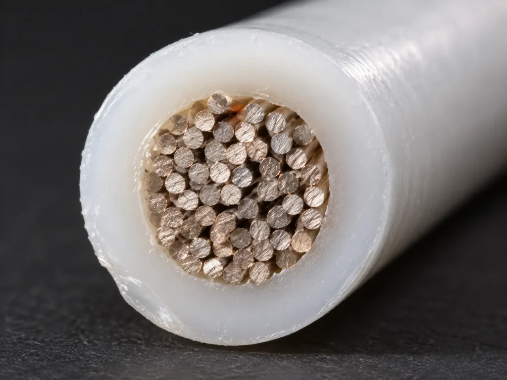
The verified range is 26 AWG through 4/0 AWG, solid or stranded round. That is permitted construction scope rather than an indication that every size is stocked.
Style 1659 does not establish copper, tinned copper, bare copper, silver-plated copper or nickel-plated copper, and it establishes no strand count, strand diameter, lay length or conductor resistance. For RFQ purposes, conductor material, finish and detailed stranding are specified by the buyer where controlled.
Optional Mica Tape Wrap
Mica tape is optional and is not presented here as standard. No claim is made that it provides fire survival, circuit integrity, 450°C service, a higher Style temperature rating, mechanical protection or arc resistance — the Style data supports none of those.
For a thermal-equipment RFQ, the question to answer is simply whether the optional mica tape construction is required, and the requirement comes from the drawing rather than from the presence of heat.
Optional Treated Glass Braid
The treated glass braid is likewise optional rather than mandatory. No abrasion resistance, cut-through resistance, higher temperature rating, mechanical reinforcement or improved heat resistance is claimed for it. Where the customer construction requires it, it is confirmed separately.
Optional Oil and Gasoline Resistance
Style 1659 includes an optional Oil Res 80°C rating. Not all Style 1659 is oil resistant, not all thermal-equipment constructions carry this rating, and PTFE does not automatically provide the optional UL oil rating.
Where thermal equipment involves oil exposure — a heated oil circuit, a lubricated mechanism nearby — ask whether the optional Oil Res 80°C rating is required and confirm it for the ordered construction.
The Gasoline Resist rating is likewise optional and is not claimed universally. On a thermal-equipment page it remains a secondary optional specification rather than a general chemical-resistance statement.
Horizontal Flame
The verified Style flame designation is Horizontal Flame. VW-1, FT1, vertical flame and any other named flame classification are not claimed here, and any additional flame requirement is separately confirmed.
Thermal Equipment Application Contexts
The commercial contexts this page addresses are internal wiring in thermal-control equipment, internal leads in electrically heated equipment assemblies, internal wiring in temperature-controlled OEM equipment, and internal component connections located in heat-influenced equipment sections.
These are buyer contexts rather than UL-approved end-use classifications, and no application is approved simply because Style 1659 exists. Where thermal-control equipment is involved, nothing here claims temperature-control accuracy, sensor compatibility, heater-control performance or temperature stability — those are system functions, not Style 1659 characteristics.
The official Use is internal wiring. Style 1659 is not building wiring, field wiring, branch circuits, tray, conduit, raceway, external equipment cables, portable cord, power supply cord or general installation cable.
Dimensions, Current and Performance
Style 1659 does not define one universal finished OD. Actual dimensions depend on the AWG, the actual conductor construction, the extrusion, whether the optional mica tape is present, whether the optional treated glass braid is present, and manufacturing tolerance. Where routing or terminal entry is dimension-controlled, request the maximum OD and the OD tolerance.
No universal current rating or ampacity table appears here, because the Style defines none and ampacity is not calculated from AWG alone. No heater wattage, motor rating, maximum current, current density or power output is published, since those depend on the complete electrical design.
No minimum bend radius, flex-cycle figure, continuous-flex capability or flexibility claim is made, and no figure is offered for dielectric strength beyond 600 Vac, thermal aging life, thermal cycling life, chemical-resistance values, abrasion resistance, cut-through resistance, corona resistance, partial-discharge performance, arc resistance, UV resistance or water resistance.
Style Selection
Mica-based UL Styles have their own construction, temperature, voltage and Use requirements, and Style 1659 is not described here as a middle ground between ordinary wire and mica wire, nor is mica presented as automatically superior for hotter applications. A simple temperature hierarchy across Styles would skip the construction and Use differences that actually decide the question.
The same applies to polymer family. UL 10362 and UL 1332 are not offered here as direct substitutions on the basis that a design calls for PFA or FEP — each AWM Style has independent construction, rating, Use, insulation requirements and optional features, and selection is made against the customer’s actual specification.
What Style 1659 Does Not Define
- Conductor material and conductor plating
- Strand count, strand diameter and conductor resistance
- Finished OD and OD tolerance
- Ampacity and current rating
- Bend radius, flex life and service life
- Colour
- Terminal, connector and cut length
- MOQ, stock and lead time
Each requires the customer specification, verified SKU documentation, the applicable qualified construction, or commercial confirmation.
Common Procurement Errors
- One insulation thickness assumed for the whole Style. Three groups apply.
- 20/18 mil values used across the full range. They cover 26–10 AWG only.
- A 9 AWG insulation thickness invented. The official table has no such row.
- Stranded tinned copper assumed. Conductor material is not set at Style level.
- 250°C read as a guaranteed continuous lifetime. It is a rating.
- A 250°C wire assumed able to touch a 250°C heating element. Position is a design question.
- Thermal equipment assumed to mean fire-resistant wiring. Different requirement entirely.
- Mica tape assumed standard. It is optional.
- Treated glass braid assumed standard. Also optional.
- Every construction assumed Oil Res 80°C or Gasoline Resist. Both are optional ratings.
- A universal finished OD or ampacity assumed.
- An AWM Style selected only from insulation-polymer type.
RFQ Checklist
- UL AWM Style 1659 requirement
- Required AWG
- Solid or stranded round conductor
- Required conductor material and finish or plating
- Stranding, if controlled
- Required temperature rating
- Expected maximum temperature at the installed wire location
- 600 Vac requirement
- PTFE / TFE construction requirement
- Optional mica tape requirement
- Optional treated glass braid requirement
- Oil Res 80°C requirement, if applicable
- Gasoline Resist requirement, if applicable
- Maximum finished OD, if controlled, and OD tolerance
- Insulation colour
- Equipment type
- Wire installation location inside the equipment
- Heat-source relationship
- Terminal or connector interface, if controlled
- Customer drawing or existing wire specification
- Quantity, packaging and destination
- Required compliance documentation
No requested construction is presented here as automatically available.
UL Marking and Documentation
Material is supplied as UL-recognized component wire where supplied under qualified manufacturing scope, and UL marking is applied according to the confirmed ordered construction. The Style-level marking designation is General.
CSA AWM, FT1, VW-1 and dual UL / CSA certification are not claimed here; any additional certification depends on the ordered construction. Applicable RoHS / REACH documentation can be confirmed according to the ordered construction.