UL 3304 for Gas Range Electronic Ignition Wiring
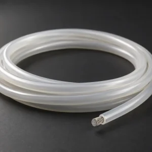
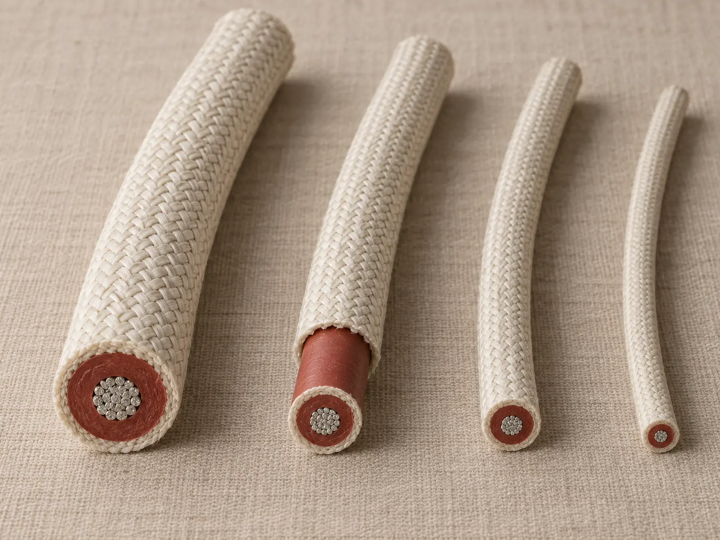
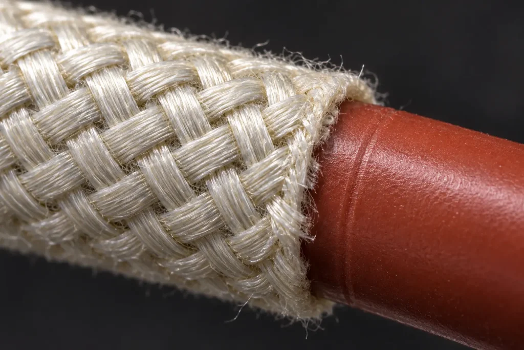
UL AWM Style 3304 is a single conductor with extruded insulation, rated 200°C and 10,000 Vac with Horizontal Flame, built as extruded silicone rubber insulation with a fiberglass braid covering. The Style conductor range is 22 AWG through 12 AWG, solid or stranded round.
This page addresses one procurement role: sourcing a Style 3304 lead for protected internal electronic ignition wiring in a gas range. The full 22–12 AWG range appears here because that is the verified Style range, not because a particular gauge distinguishes this page.
Gas ranges are named in the official Use, which makes this application context unusually well grounded. The Use also carries a condition — protection from damage during handling, installation and servicing of the appliance — and that condition is part of the sentence rather than a qualifier attached to it.
Verified UL Style 3304 Ratings and Construction
| Parameter | Style-level information |
|---|---|
| UL AWM Style | 3304 |
| Product description | Single Conductor with Extruded Insulation |
| Temperature rating | 200°C |
| Voltage rating | 10,000 Vac |
| Flame | Horizontal Flame |
| Conductor size | 22 AWG–12 AWG |
| Conductor form | Solid or Stranded Round |
| Insulation | Extruded SR / Silicone |
| Minimum average insulation thickness | 40 mils |
| Minimum thickness at any point | 36 mils |
| Covering | Fiberglass Braid |
| Marking | General |
| Official Use | Internal Wiring of Electronic Ignition or similar application in Gas Ranges or Gas or Fuel Oil Burner Systems where protected from damage during handling, installation and servicing of the appliance |
Everything above is Style-level. The two insulation figures are separate requirements rather than a range: 40 mils governs the average across the wall, 36 mils sets a floor at every individual point on it.
What the 22–12 AWG Range Actually Establishes
The Style conductor statement defines two things: the permitted size range and the permitted form. It does not define what the conductor is made of.
Conductor material and plating are not established at Style level, so copper, bare copper, tinned copper, silver-plated copper and nickel-plated copper are none of them assumed on this page. Neither are strand count, strand diameter, conductor diameter, conductor resistance, lay length, ampacity or current rating. Those are properties of an ordered construction, and they are listed later as things to specify rather than things to read off a Style record.
The same applies to finished outside diameter. It is not calculated here from a nominal conductor diameter plus twice the insulation thickness — the braid covering and the actual conductor construction both affect the result.
Gas Range Ignition Procurement Context
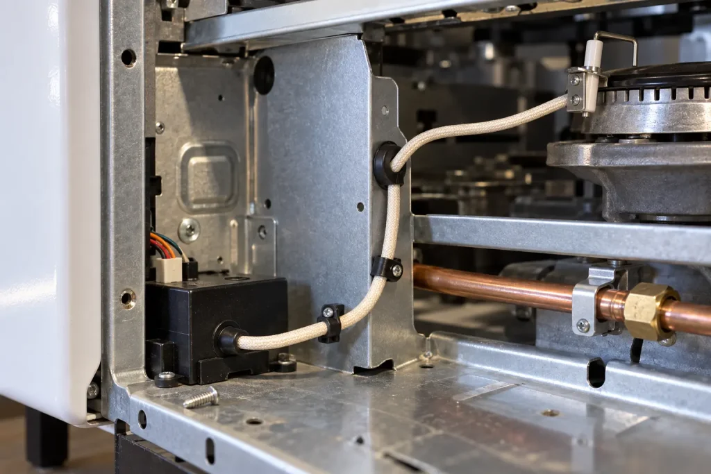
In a gas range the ignition lead typically runs between an ignition module and one or more surface or oven electrodes, inside the appliance body, along a path fixed at build. The sourcing questions that follow from that are practical and specific.
The lead length is usually set by the appliance layout rather than chosen. The routing path determines whether the lead crosses sheet-metal edges, passes through panels, or runs near a burner assembly. The termination at each end is defined by the module connector and the electrode interface, both of which come from the appliance design. And the space the lead occupies matters where it shares a channel with gas tubing or other wiring.
None of these are additional UL-approved uses. They are the information that turns “we need Style 3304” into something quotable against a specific construction.
Protection From Damage During Handling, Installation and Servicing
The protection condition in the official Use names three activities, and the third is the one most often overlooked at specification stage.
Handling covers the appliance factory. Installation covers the point where the range is placed, levelled and connected. Servicing covers everything afterwards — a technician removing a back panel, pulling a module, reaching past the ignition lead to access something else. A lead that is entirely protected in the assembled appliance may be exposed during that last activity, and the Use makes protection across all three the condition of the application.
That obligation sits with the appliance design. Nothing here claims that the fiberglass braid covering discharges it, and no abrasion, cut, impact or crush performance is attributed to the braid, because the Style information establishes none. Nor does this discussion extend the Style toward field wiring or exposed installation: Style 3304 remains internal appliance wiring.
Dimensional and Termination Requirements
The Style record does not establish a finished OD, an OD tolerance, a terminal type, a connector type, a stripping specification or a finished lead configuration. Where any of these is controlled by the appliance design, it belongs in the enquiry:
- Finished OD constraint or maximum OD where routing space is limited
- Terminal or termination requirements at each end
- Stripping requirements, where the lead is supplied processed
- Connector interface requirements
- Routing constraints affecting lead geometry
These are confirmation fields for an ordered construction, not fixed Style 3304 specifications, and nothing is assumed on the buyer’s behalf.
Why “10kV, 200°C” Is Not Enough to Match a Substitute
This deserves direct attention, because matching on ratings alone is the most common route to an incorrect substitution in ignition leads.
A lead offered as equivalent must be evaluated against the required UL Style, the actual construction, the appliance design, the dimensions, the termination requirements, the marking requirements and the applicable equipment-level approval. Two products can share a temperature and voltage rating and still be different constructions with different dimensions and different approval status in the appliance.
No other Style is automatically interchangeable with Style 3304, and none is presented that way here.
UL 3304 and UL 3573 Are Different Constructions
This point illustrates the one above, because the two Styles make the ratings-matching problem concrete.
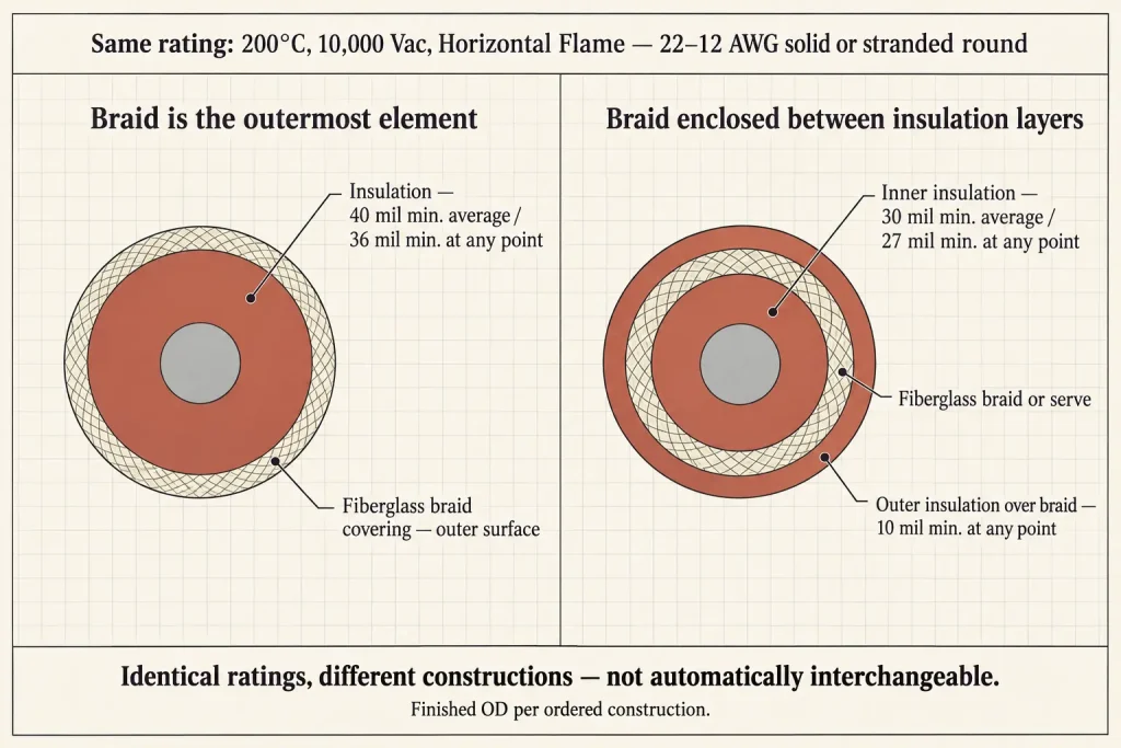
Style 3304 and Style 3573 share the same rating — 200°C, 10,000 Vac, Horizontal Flame — and the same 22–12 AWG solid or stranded round conductor range. What differs is the construction itself.
Style 3304 has a single extruded SR / silicone insulation at 40 mils minimum average and 36 mils minimum at any point, with a fiberglass braid covering over it. Style 3573 is built the other way around: an inner silicone insulation at 30 mils minimum average and 27 mils minimum at any point, a fiberglass braid or serve over that, and then an outer insulation over the braid at 10 mils minimum at any point. In Style 3304 the braid is the outermost element. In Style 3573 the braid is enclosed between two silicone layers.
Neither is presented here as better. They are different constructions, with different outer surfaces and different dimensional outcomes, and neither is automatically interchangeable with the other. Where a design has been approved around one, substituting the other is a construction change requiring its own evaluation. Style 3573 has its own category page where its construction is addressed in its own terms.
The 200°C and 10,000 Vac Ratings
Style 3304 is rated 200°C. That rating applies to the wire, and it is not stated here as a continuous-operation figure because the Style record does not use that wording. It also does not establish that connectors, electrodes, the ignition module or adjacent appliance components are rated 200°C — those are separate design questions.
The voltage rating is 10,000 Vac and should be written that way where precision matters. It is not restated as 10,000 Vdc, a 10kV peak value, an impulse voltage, a spark-test voltage or a dielectric test voltage, and no ignition-system voltage figure beyond the verified wire rating appears on this page. Whether a given ignition module, electrode design, spark waveform or appliance architecture is suitable is not something the wire rating establishes.
Flame Classification
The Style record supports Horizontal Flame. VW-1 is a separate classification and is not claimed here, nor is Horizontal Flame silently converted into it.
Where a project specification requires vertical flame capability, that depends on a separately confirmed construction and order requirement rather than on the Style 3304 rating.
What UL Style 3304 Does Not Define
- Conductor material and conductor plating
- Detailed strand construction — strand count, strand diameter, lay length
- Conductor diameter and conductor resistance
- Ampacity or current rating
- Finished OD and OD tolerance
- Bend radius, flex-cycle life and flexibility class
- Insulation or covering color
- Terminal type, connector type and finished lead configuration
- Reel length, packaging, MOQ, stock status and lead time
Each requires confirmation for the ordered construction. None is available by reading the Style record.
RFQ Checklist for a Gas Range Ignition Lead
- UL Style 3304 requirement
- AWG within the 22–12 AWG Style range
- Solid or stranded round requirement
- Requested conductor material
- Requested conductor plating or finish
- Requested detailed strand construction, if controlled
- Required finished OD or maximum OD constraint
- Insulation / covering color requirements
- Lead length or cut-length requirement, if applicable
- Termination or stripped-end requirements
- Terminal / connector interface requirements
- Actual gas range ignition application
- Internal routing and protection conditions
- Required wire marking
- Quantity
- Packaging / reel requirement
- Destination
- Required compliance or order documentation
Each item is something to provide or confirm, not something available by default.
UL Marking and Documentation Boundaries
Material is supplied as UL-recognized component wire where supplied under qualified manufacturing scope, and UL marking is applied according to the confirmed ordered construction. The Style-level marking designation is General.
CSA AWM, FT1 or dual UL / CSA certification are not claimed here — any additional certification depends on the ordered construction and has to be confirmed as part of it. Applicable RoHS / REACH documentation can be confirmed according to the ordered construction.
Application Boundary
Style 3304 is an AWM internal-wiring construction. It is not building wire, field wiring, branch-circuit wiring, tray cable, conduit wire, portable cord or general power distribution cable, and the gas range discussion on this page is buyer application context within internal appliance wiring.
The presence of an ignition system in a piece of equipment does not by itself bring that equipment within the Use. The official wording names electronic ignition or similar application in gas ranges or gas or fuel oil burner systems, with the protection condition attached, and that is the boundary this page works within.
Sending an Enquiry
For a gas range ignition lead, the most useful enquiry states the Style, the AWG, the conductor form, any controlled conductor material or finish, the dimensional constraint, the termination requirement at each end, and the lead length. With those in hand the request can be matched to a qualified Style 3304 construction rather than to a Style number.