Selecting a UL 3321 Construction for Your Routing Condition
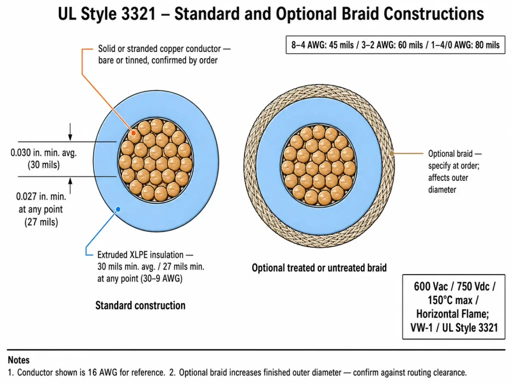
UL AWM Style 3321 is an extruded XLPE wire rated 150°C maximum at 600 Vac / 750 Vdc, covering 30 AWG through 4/0 AWG, designated for the internal wiring of appliances. Within that single Style, the conductor type, the presence or absence of the optional braid covering, and the AWG-dependent insulation wall all change the finished wire’s diameter, stiffness, and handling behaviour — and the right combination depends on how the wire is actually routed inside the appliance assembly.
This page is organised around that question. Buyers who want the full Style overview, insulation wall table, and XLPE-versus-PVC selection notes should start from the UL 3321 XLPE Hook-up Wire product page. This page covers how to translate a routing condition into a specific ordered construction before requesting a quotation.
Three Routing Conditions and What They Change
Most enclosed appliance internal wiring falls into one of three routing conditions. Each places different demands on the wire construction.
Bound harness routing
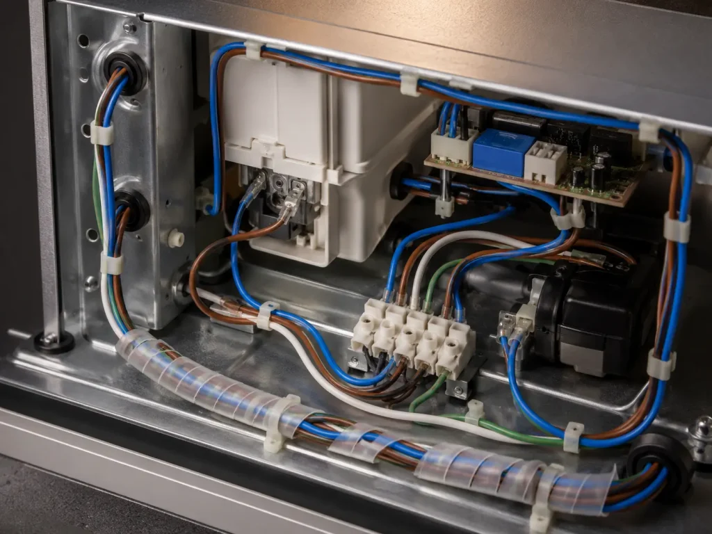
Where several UL 3321 leads are bundled together and routed as a harness along the chassis, the dominant constraint is bundle diameter and the ability of each lead to conform to the harness path without introducing stiffness at the bind points. Stranded conductor is generally specified here, because the harness is formed and positioned during assembly rather than following a pre-set straight path. Finished outer diameter matters cumulatively — a bundle of eight leads at 30 mils wall behaves very differently from the same eight leads at 45 mils. Where the harness is bound with a spiral wrap or sleeve, the optional braid covering is often unnecessary, since the wrap already provides the surface protection at contact points.
Fixed single-lead routing
Where individual leads run point-to-point and are clipped at intervals along a fixed path, the wire is positioned once during assembly and does not move afterwards. Both solid and stranded conductor are within the UL Style 3321 scope for this condition, and solid conductor may be specified where the routing path is straight and the termination method accommodates it. The relevant construction question here is usually the clip and grommet interface: confirm the finished outer diameter against the internal diameter of the routing clips and chassis pass-through grommets specified in the assembly, particularly when the lead sits in the 8–4 AWG or larger wall classes where the insulation wall steps up significantly.
Compact section routing
Where leads run through a confined region of the assembly — behind a control module, between a component and the chassis wall, or through a narrow channel — available clearance is the governing constraint. In this condition the AWG-dependent wall class is the first thing to check, since the difference between the 30 mils wall at 30–9 AWG and the 45 mils wall at 8–4 AWG translates directly into finished diameter. The optional braid covering also adds to the outer diameter and should be specified only where the routing genuinely requires the additional surface protection at a contact point, not as a default.
Construction Selection Reference
| Routing condition | Conductor | Optional braid | Confirm at enquiry |
|---|---|---|---|
| Bound harness | Stranded generally specified | Often not required where a wrap or sleeve is used | Lead count, per-lead AWG, cumulative bundle diameter, colour scheme for identification |
| Fixed single lead | Solid or stranded, both within Style scope | Specify where a clip or pass-through contact point requires it | Finished OD against clip and grommet internal diameter; termination method |
| Compact section | Stranded generally preferred for tight paths | Specify only where clearance permits the added diameter | Available clearance against AWG wall class; whether the AWG sits either side of a wall-class boundary |
Conductor surface finish — bare or tinned copper — is an order-confirmed construction detail in all three conditions and is driven by the termination method used in the assembly rather than by the routing path. Final conductor construction, finished dimensions, insulation colour, marking, spool format, and documentation all depend on the confirmed order specification.
UL AWM Style 3321 — Reference Parameters
| Parameter | Value per UL Style 3321 file |
|---|---|
| UL AWM Style | 3321 |
| UL Subject / Section | 758, Section 3 |
| Temperature rating | 150°C maximum |
| Voltage rating | 600 Vac / 750 Vdc |
| Conductor range | 30 AWG – 4/0 AWG, solid or stranded |
| Insulation | Extruded XLPE (cross-linked polyethylene) |
| Wall — 30–9 AWG | 30 mils (0.76 mm) min avg / 27 mils (0.69 mm) min at any point |
| Wall — 8–4 AWG | 45 mils (1.14 mm) min avg / 40 mils (1.02 mm) min at any point |
| Wall — 3–2 AWG | 60 mils (1.52 mm) min avg / 54 mils (1.37 mm) min at any point |
| Wall — 1–4/0 AWG | 80 mils (2.03 mm) min avg / 72 mils (1.83 mm) min at any point |
| Optional covering | Treated or untreated braid — specify at order |
| Conductor material | Copper — bare or tinned, confirmed by order |
| Flame rating | Horizontal flame; VW-1 vertical flame test available |
| UL Recognition | UL Recognized Component — file on record |
| Permitted use | Internal wiring of appliances |
| Marking | Per UL Subject 758 marking requirements; confirmed according to the qualified construction |
| RoHS / REACH | Documentation available on request, where applicable |
Application Boundary
UL AWM Style 3321 is designated for the internal wiring of appliances. All three routing conditions described above assume the wire remains within an enclosed appliance assembly and is protected from mechanical damage along its entire path by the equipment structure — clips, ducts, grommets at every chassis pass-through, and adequate separation from moving components. The Style is not designated for building wiring, field wiring, external cabling, or any routing outside the enclosed assembly. Whether a specific UL 3321 construction is acceptable for a given installation is determined at the equipment design and equipment-level evaluation stage, together with current-carrying capacity and thermal derating.
When 150°C XLPE Is the Right Class
Specify UL AWM Style 3321 where the appliance internal wiring location requires a 150°C maximum XLPE construction. Where the routing location operates within a 125°C limit, UL 3271 XLPE Wire (125°C / 600 Vac / 750 Vdc, 30 AWG–2000 kcmil) covers the same voltage class at the lower temperature grade and extends to larger kcmil sizes. Where the equipment design calls for silicone rubber rather than XLPE — typically for handling flexibility or a 200°C class — UL 3135 Silicone Wire should be evaluated instead. Where fluoroplastic insulation is specified by the design, UL 1332 FEP Wire and UL 10362 PFA Wire cover the FEP and PFA options. These Styles are not interchangeable — the insulation material, temperature rating, voltage rating, and permitted use must each match the actual design requirement.
The full range is available under XLPE Wire and AWM Wire.
Requesting a Quotation
Send the following with your enquiry so the available construction can be confirmed against the applicable UL Style file:
- Routing condition: bound harness, fixed single lead, or compact section
- AWG size or sizes required, and lead count if ordering for a harness
- Conductor construction: solid or stranded; bare or tinned copper
- Optional braid requirement: none, treated, or untreated
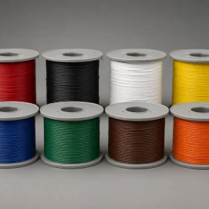
- Insulation colour, including any colour identification scheme across multiple leads
- Quantity in metres, spool length or cut-to-length format
- Documentation requirements: UL AWM Style documentation, RoHS, REACH, Certificate of Origin
Minimum order quantity 100m per colour per AWG. Mixed-AWG orders accepted on a single shipment. B2B quotation response within 12 hours. HS Code: 8544.49.