UL 3321 for Internal Leads in Commercial and Industrial Appliances
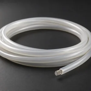
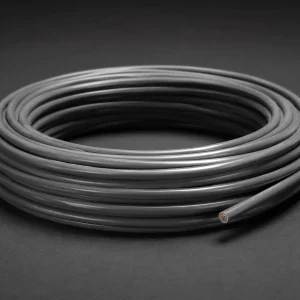
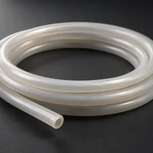
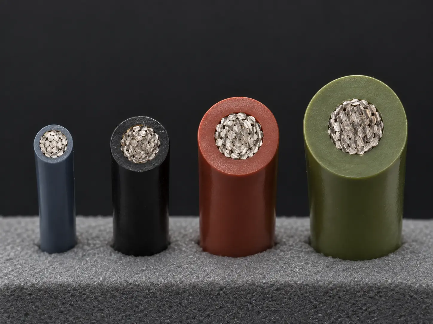
UL AWM Style 3321 is a single conductor with extruded insulation, rated 150°C, 600 Vac and 750 Vdc, with Horizontal Flame. The conductor range is 30 AWG through 4/0 AWG, solid or stranded, with extruded XLPE insulation and an optional treated or untreated braid.
The official Use for Style 3321 is internal wiring of appliances. This page addresses that requirement where the appliance itself is in commercial or industrial service — internal component leads inside equipment built for a commercial kitchen, a laundry operation, a processing line or a similar working environment rather than a domestic setting.
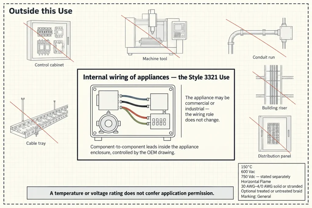
The appliance may be industrial. The wiring role does not change: it remains internal component wiring inside the appliance, controlled by the OEM’s electrical drawing.
What “Industrial” Can and Cannot Modify Here
This distinction deserves its own section, because it is where specifications most often drift.
The official Use names appliances. It does not name equipment, machinery, systems or installations. So “industrial” is usable on this page when it describes the appliance — an industrial appliance, a commercial appliance, an OEM appliance assembly built for industrial service. It is not usable as an application in its own right.
Style 3321 is therefore not presented here as generally approved or suitable for industrial control cabinets, factory machinery, production-line field wiring, PLC cabinets, facility electrical systems, machine-tool field wiring, building wiring, branch circuits, tray, conduit, raceways or premises wiring. None of those is an appliance, and none of them is brought within the Use by the 150°C or 600 Vac rating.
A rating does not confer application permission. Two products can share a temperature and voltage figure while belonging to entirely different wiring categories with different rules.
Verified UL Style 3321 Ratings and Construction
| Parameter | Style-level information |
|---|---|
| UL AWM Style | 3321 |
| Construction | Single conductor with extruded insulation |
| Temperature rating | 150°C |
| AC voltage rating | 600 Vac |
| DC voltage rating | 750 Vdc |
| Flame | Horizontal Flame |
| Conductor size range | 30 AWG–4/0 AWG |
| Conductor form | Solid or Stranded |
| Insulation | Extruded XLPE |
| Covering | Optional treated or untreated braid |
| Marking | General |
| Official Use | Internal wiring of appliances |
Minimum Insulation Wall by Conductor-Size Group
| Conductor size group | Minimum average thickness | Minimum thickness at any point |
|---|---|---|
| 30 AWG–9 AWG | 30 mils | 27 mils |
| 8 AWG–4 AWG | 45 mils | 40 mils |
| 3 AWG–2 AWG | 60 mils | 54 mils |
| 1 AWG–4/0 AWG | 80 mils | 72 mils |
The minimum insulation-wall requirement changes with the conductor-size group. There is no single Style 3321 wall thickness, and describing the Style as having 30 mil insulation is accurate only within the first group.
Each group states two separate requirements rather than a range. The first governs the average across the wall; the second sets a floor at every individual point on it. Both belong in a specification.
AC and DC Ratings Are Stated Separately
Style 3321 carries 600 Vac and 750 Vdc. Both are verified Style-level figures, and they describe different conditions.
750 Vdc is not restated here as 750 Vac, as “750V AC/DC”, as a generic 600/750V power cable designation, or as a 600–750V continuous rating. Nor is 600 Vac characterised as a stronger structure — it is a rating, not a construction attribute.
Commercial and industrial appliances frequently contain both AC and DC internal sections, particularly where electronic control and power conversion are involved. The enquiry should state which electrical condition applies at the lead position, because that determines which of the two figures is the relevant one.
The 150°C Rating
150°C is the Style-level temperature rating and applies to the wire.
It is not stated here as guaranteeing 150°C continuous service for every installed condition, and no long-life operation at that temperature is claimed. The actual appliance design and the installed conditions at the wire’s position remain engineering considerations that the rating does not settle. Ambient temperature, proximity to heat-generating components, enclosure ventilation and duty pattern are all part of that evaluation.
Selecting AWG Across a 30 AWG to 4/0 AWG Range
The range is unusually wide for one Style, and correct AWG selection is controlled by the appliance electrical design and the customer specification rather than by the Style.
No ampacity table appears on this page. Larger AWG sizes are not described here as automatically high-current, because that would require separately verified engineering data the Style record does not supply. Nor do all sizes within the Style share similar physical dimensions — a 30 AWG conductor and a 4/0 conductor are different products in every practical respect.
The insulation-wall requirement is the reason AWG has to be settled before quotation: it becomes progressively thicker through the larger-conductor groups, so the Style number alone does not identify which construction is being requested.
The Optional Braid
Style 3321 permits an optional treated or untreated braid. It is not present in every construction and is not mandatory.
Braid material, thickness, colour, abrasion rating, mechanical-strength effect, temperature effect and service-life effect are not established by the Style record, and none is stated here. The buyer should state whether an optional braid is required in the ordered construction, together with anything the drawing controls about it.
Conductor Requirements Are RFQ Items
The official Style information establishes the 30 AWG–4/0 AWG range and the solid or stranded form. It establishes nothing else about the conductor.
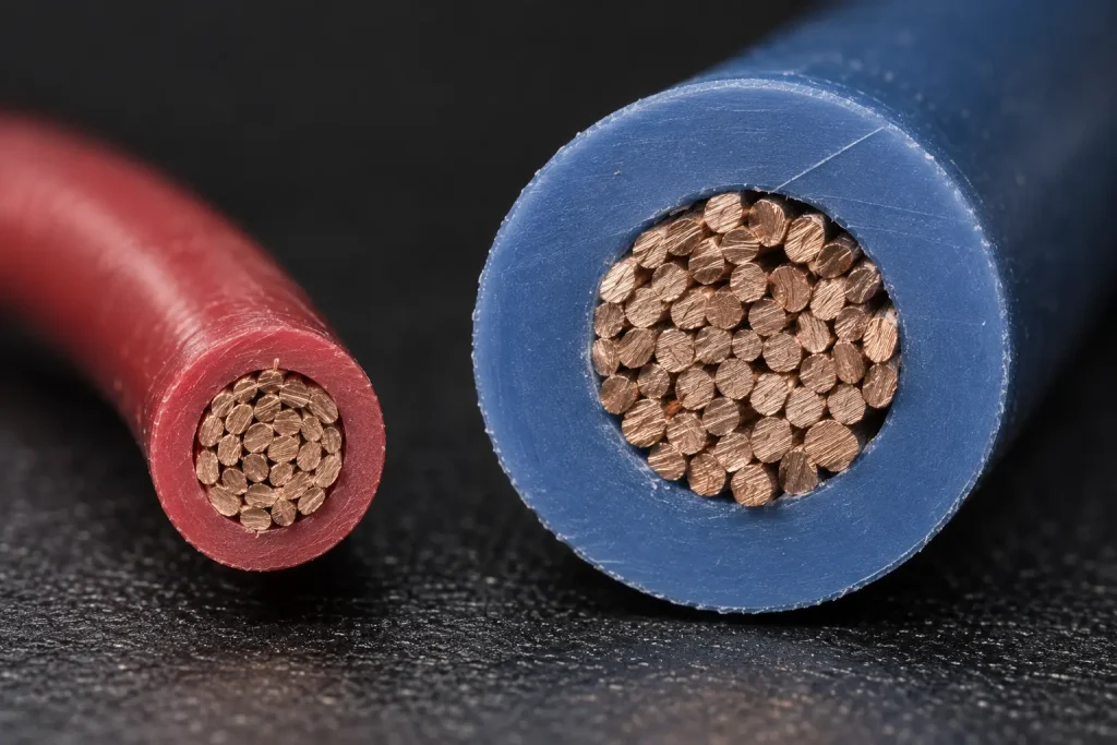
Copper, tinned copper, bare copper, silver-plated copper and nickel-plated copper are none of them established at Style level, and no strand count, individual strand diameter, conductor diameter, lay length, conductor resistance or ampacity is stated here. Where an appliance drawing requires a particular conductor material, finish or stranding, each is a confirmation item.
Internal Lead Routing Inside the Appliance
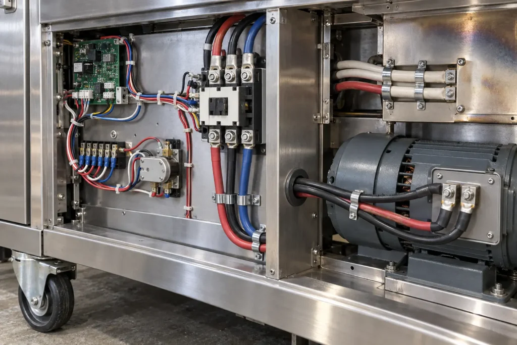
Routing on this page means routing within the appliance enclosure: protected component-to-component lead paths, fixed internal lead positions inside the assembly, and drawing-controlled internal appliance wiring.
It does not mean lead routing through machinery, machine wiring, field-installed lead routing, plant wiring or control-cabinet field wiring. Those describe conductors installed to different rules, and the fact that a commercial appliance sits in an industrial facility does not bring the facility’s wiring within this Style’s Use.
Dimensional Control
No universal finished outside diameter is published for Style 3321. The Style defines minimum insulation-wall requirements, not a finished-wire diameter, and the finished dimensions depend on the specific ordered construction.
Where the appliance design controls dimensions, provide the required AWG, the maximum finished OD, the OD tolerance where applicable, the routing clearance, the terminal interface, the connector interface and the optional braid requirement.
Style 3321 is not described here as universally compact, thin-wall, small-diameter or space-saving, and no dimensional value is invented.
Bulk Wire and a Processed Lead
This page concerns Style 3321 single-conductor bulk wire. A finished appliance lead is a different deliverable.
The Style defines no cut length, strip length, terminal, connector, ferrule, crimp, wire seal, finished lead assembly or completed harness. Where processed leads are required, those requirements are separately specified and confirmed; cutting, stripping, crimping and termination are not presented here as automatically included services.
What Style 3321 Does Not Define
- Conductor material and conductor plating
- Strand count, strand diameter and conductor resistance
- Ampacity
- Finished OD and OD tolerance
- Colour
- Terminal, connector, cut length and strip length
- Packaging, reel length, MOQ, stock and lead time
Each comes from the ordered construction, the customer drawing, verified SKU documentation or separate commercial confirmation.
Common RFQ Mismatches
- “UL3321 industrial wire” requested without confirming the application is appliance internal wiring. The Use names appliances.
- Style 3321 requested with no AWG. Four insulation groups sit inside the range.
- Tinned copper assumed from the Style number. Conductor material is not set at Style level.
- 30 mil insulation assumed for all sizes. It applies to the 30–9 AWG group only.
- Optional braid assumed to be standard. It is present only where ordered.
- One universal finished OD assumed. OD depends on size, construction and braid.
- 750 Vdc read as 750 Vac. The AC rating is 600 Vac.
- Appliance internal wire confused with control-cabinet field wiring. Different categories.
- Bulk wire confused with a terminated appliance lead. Different scopes.
- Conductor finish or dimensional limits omitted where the drawing controls them.
RFQ Checklist
- UL AWM Style 3321 requirement
- Required AWG within 30 AWG–4/0 AWG
- Solid or stranded requirement
- Required conductor material
- Required conductor finish or plating
- Detailed stranding, where controlled
- Insulation colour
- Optional treated or untreated braid required: yes / no
- Finished OD or maximum OD, if controlled
- Commercial or industrial appliance type
- Internal installation location
- Required AC or DC electrical condition
- Temperature requirement at the wire location
- Customer drawing or existing specification
- Cut length, if applicable
- Strip length
- Terminal or connector interface
- Marking requirement
- Quantity
- Packaging requirement
- Destination
- Required compliance documentation
These are RFQ inputs. No configuration is presented as automatically available.
Substitution
Different UL AWM Styles have independent ratings, constructions and official Uses. No Style is presented here as automatically interchangeable with Style 3321, and none is recommended on the basis of a preferred insulation material.
Any substitution requires evaluation against the required UL Style, the official Use, the temperature rating, the AC and DC voltage ratings, the AWG, the conductor construction, the insulation system, the optional covering, the dimensions, the termination requirements and the equipment specification.
UL Marking and Documentation
Material is supplied as UL-recognized component wire where supplied under qualified manufacturing scope, and UL marking is applied according to the confirmed ordered construction. The Style-level marking designation is General.
CSA AWM, FT1, VW-1 and dual UL / CSA certification are not claimed here; any additional certification depends on the ordered construction. Applicable RoHS / REACH documentation can be confirmed according to the ordered construction.
Flame Classification
The verified Style-level designation is Horizontal Flame. VW-1 and FT1 are separate classifications and are not claimed here; Horizontal Flame is not converted into either, and no vertical-flame performance is implied. Any separately confirmed vertical-flame construction remains order-specific.