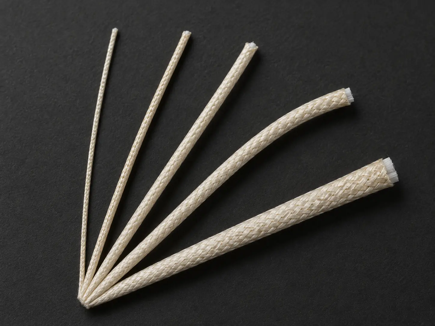
UL 5360 200°C Mica Glass Braid Wire Overview
UL AWM Style 5360 is a single conductor construction with other-than-extruded insulation, built as nonextruded mica tape with a glass braid treated with silicone varnish or TFE finish. The Style rating is 300 Vac with Horizontal Flame, and the Style permits either a 200°C or a 450°C temperature rating.
This page is positioned around the 200°C branch, in the 30–12 AWG construction band, for protected fixed internal wiring in heating equipment. Style 5360 also includes 450°C-rated constructions — that is a real part of the Style, not an omission — but the specification, keyword focus and RFQ guidance on this page are written for the 200°C requirement. The required temperature rating comes from the equipment specification, not from a preference between the two.
The Style’s official Use carries two conditions that govern almost every sourcing decision here: the wiring must not be subjected to repeated flexing, and it must be protected from mechanical abuse. Both have their own sections below.
UL 5360 Technical Specifications
| Parameter | Style-level information |
|---|---|
| UL AWM Style | 5360 (UL 758) |
| Description | Single conductor with other-than-extruded insulation |
| Style temperature options | 200°C or 450°C |
| This product page focus | 200°C |
| Voltage rating | 300 Vac |
| Flame | Horizontal Flame |
| Complete Style range | 30 AWG–4/0 AWG |
| Page construction band | 30–12 AWG |
| Conductor form | Solid or stranded in sizes 26–8 AWG; larger sizes stranded only |
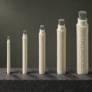
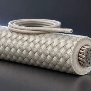
| Insulation | Nonextruded mica tape with glass braid |
| 30–12 AWG mica tape | 12 mil minimum average total thickness |
| 30–12 AWG treated glass braid | 7 mil minimum average thickness |
| Glass braid treatment | Silicone varnish or TFE finish |
| Optional shield | 36–30 AWG Type “A” nickel or 27 percent minimum nickel coated copper — confirm if required |
| Multi-conductor assembly | Style-supported, maximum assembly OD 1.500 inches — confirm if required |
| Official Use | Internal wiring where not subjected to repeated flexing and protected from mechanical abuse, and where the acceptability, including current-carrying capacity, has been determined by Underwriters Laboratories Inc. |
Why 30–12 AWG Is a Real Construction Band
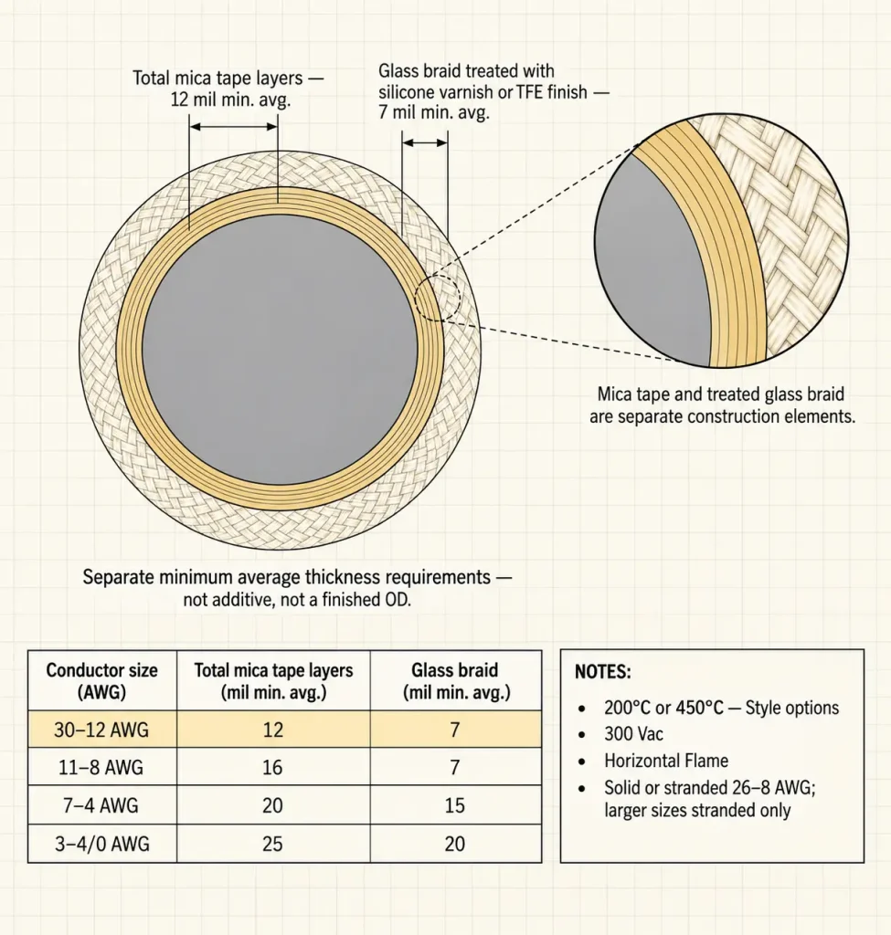
The 30–12 AWG grouping used on this page is not a size split invented for search. It is a construction band defined within the Style itself: every conductor size from 30 AWG through 12 AWG carries the same stated minimum average requirements — 12 mils total mica tape layers and 7 mils treated glass braid.
What the shared band does not mean is that constructions inside it are otherwise identical. Finished OD, current capacity, conductor resistance, strand construction and termination all still vary with the actual conductor size and the ordered construction. The band fixes two minimum average thickness values; it does not fix a product.
The Four UL 5360 Construction Bands
| AWG band | Min. avg. total mica tape | Min. avg. treated glass braid |
|---|---|---|
| 30–12 AWG | 12 mil | 7 mil |
| 11–8 AWG | 16 mil | 7 mil |
| 7–4 AWG | 20 mil | 15 mil |
| 3–4/0 AWG | 25 mil | 20 mil |
The table is a construction reference showing how conductor size affects the specified construction. Thicker specified construction in a larger band does not mean higher current capacity, a higher temperature rating, better mechanical protection or better electrical performance, and none of those are claimed here. Note also that the braid requirement does not step at every band — 30–12 AWG and 11–8 AWG share the same 7 mil braid value while the mica requirement changes.
Do Not Add the Two Thickness Figures
The mica tape and the treated glass braid are separate construction elements with separate minimum average thickness requirements. 12 and 7 do not combine into a 19 mil finished insulation, a radial insulation thickness, or a finished outside diameter.
Both are stated as minimum averages for the elements, not as a guaranteed wall for any ordered construction. Where a drawing controls a dimension, it is checked against the approved construction rather than derived from the Style table.
Nonextruded Mica Tape With Treated Glass Braid
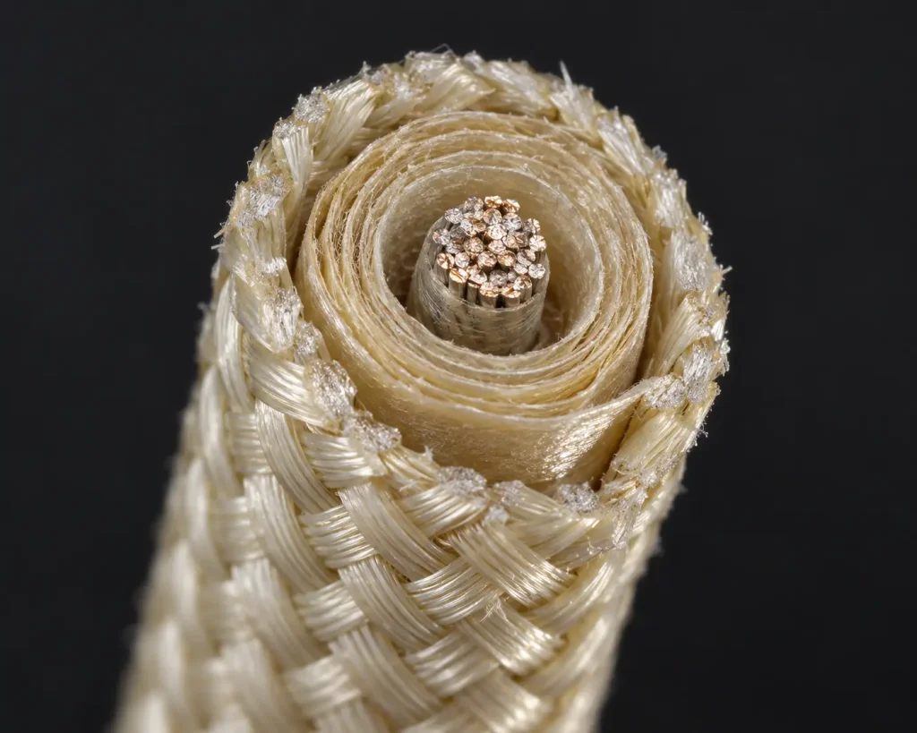
The verified construction description is nonextruded mica tape with glass braid, and the braid is treated with silicone varnish or TFE finish. Collapsing this into “mica insulation,” “fiberglass insulation” or “silicone insulation” loses the distinction between the two elements.
Two points follow from that. A silicone varnish treatment on the braid does not make this a silicone-rubber-insulated conductor. A TFE finish on the braid does not make this a PTFE-insulated wire. The treatment applies to the braid; the mica tape is the separate insulating element beneath it.
The 200°C Branch and the 450°C Option
Style 5360 states its rating as 200 or 450°C. Both are Style-supported, and neither is described here as a version of the other.
This page exists because a large share of heating-equipment enquiries specify 200°C, and a page written to that requirement is more useful than one that averages both. If the equipment specification calls for 450°C, that is a different requirement and a different construction to confirm — not an upgrade, and not automatically the better commercial choice. Take the required temperature rating from the equipment specification and state it in the enquiry.
300 Vac Is an AC Rating
The Style rating is 300 Vac and is written that way in technical content rather than as a generic “300V.” It is not restated as 300 Vdc, as a 600V peak value, as a dielectric test voltage or as an impulse voltage without separate technical evidence.
Conductor Form Is Size-Dependent
The Style states the conductor range as 30 AWG–4/0 AWG, with solid or stranded in sizes 26–8 AWG and larger sizes stranded only. That size-dependent limitation is part of the specification and is preserved here rather than simplified to “solid or stranded” across the whole range.
The 30–12 AWG band on this page therefore overlaps the 26–8 AWG solid-or-stranded window but is not identical to it. Where solid or stranded is controlled by the BOM, state which is required. Strand counts and strand diameters are not established at Style level and are not invented here.
Conductor Material and Plating Are RFQ Fields
The Style summary establishes conductor size and the size-dependent form limitation. It does not establish one universal primary conductor material or plating, so bare copper, tinned copper, nickel-plated copper and nickel conductor are none of them assumed for this page.
Where conductor material or plating is controlled by the customer BOM, state it in the enquiry so it can be confirmed against the qualified construction.
Not Subjected to Repeated Flexing
The official Use limits this Style to internal wiring not subjected to repeated flexing. That is a use condition defining what the product is for, not a disclaimer attached to it.
Style 5360 is therefore not offered here as flexible cable, high-flex wire, a continuous-flex heater lead, moving-door wire, robotic cable or drag-chain cable. Bending a wire during installation is not the same as repeated movement in service, and installation bending does not make a repeated-flex application. No bend radius, flex-cycle rating or bending-cycle count is published on this page.
Where the equipment produces ongoing movement at the wire’s position, the application needs review rather than an assumption that Style 5360 fits. State whether movement occurs when sending the enquiry.
Protected From Mechanical Abuse
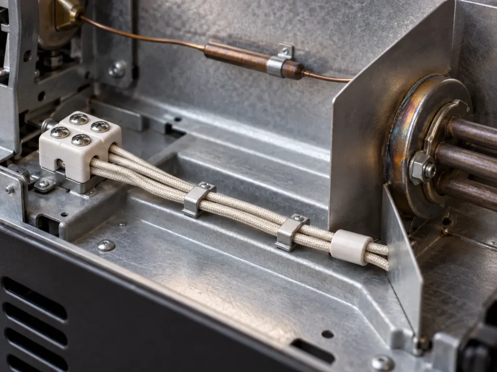
The second Use condition requires protection from mechanical abuse, which is an equipment-design obligation rather than a property of the wire.
Neither the mica tape nor the glass braid is presented here as establishing suitability for exposed wiring, abrasion without protection, sharp-edge contact, impact, crushing or open external installation, and no abrasion or mechanical-protection rating is claimed. Where the routing path crosses a metal edge, a pass-through or a clamped position, the protection method belongs in the equipment design and is worth describing in the enquiry.
Current-Carrying Capacity Is Not Published Here
The official Use refers to acceptability, including current-carrying capacity, as something determined. That is a statement about how the Style is evaluated, not an ampacity table, and the Style information does not provide one.
No amperes by AWG, heater wattage by AWG, load recommendation, power recommendation or current limit appears on this page, and nothing about current capacity is inferred from the 30–12 AWG range. Conductor size and electrical load are buyer engineering inputs.
Optional Shield
Style 5360 provides an optional shield described as 36–30 AWG Type “A” nickel or 27 percent minimum nickel coated copper. This wording belongs to the shield field and must not be read as the normal primary-conductor construction — a frequent misreading worth guarding against when writing a BOM line.
No quantified performance is attributed to the shield here. EMI attenuation, RFI performance, grounding performance, mechanical protection and abrasion resistance are not established by the Style-level information and would need separate evidence for a specific construction. Where a shield is required, state yes or no and supply the controlling specification.
Multi-Conductor Assembly Option
The Style provides for a single conductor, or for two or more of the described conductors to be cabled together with a maximum OD of 1.500 inches. A mica-glass binder and/or fiberglass fillers may be employed, and the assembly may have an overall treated glass braid.
This is a construction capability within the Style, not a description of every Style 5360 product, and this page is not a multi-core cable page. State single conductor or multi-conductor explicitly in the enquiry.
Finished OD Is Not Given by the Style Table
Finished OD is not derived here from the 12 mil mica and 7 mil braid figures, and no universal OD value is published for 30, 24, 18, 14 or 12 AWG.
Where installation space is restricted, request nominal OD, maximum OD, dimensional tolerance, routing-hole dimensions, sleeve or feedthrough dimensions and the terminal interface, taken from the approved construction.
Heating-Equipment Routing Questions
A workable enquiry for this construction usually identifies:
- Actual conductor AWG
- 200°C requirement and 300 Vac requirement
- Fixed routing location and whether movement occurs
- Mechanical protection method
- Available routing envelope
- Terminal or connector interface
- Lead length and quantity
No minimum distance from a heating element and no temperature-gradient rule is offered here — those come from the equipment’s own thermal design.
Termination Requirements
The Style does not define one universal terminal, connector, lug, crimp, strip length, sleeve or prepared-lead configuration, and none are invented here. Where finished leads are required, supply the applicable terminal or connector drawing or part number. Generic crimp and termination parameters are not published.
Official AWM Use Boundary
The official Use for Style 5360 is: Internal wiring where not subjected to repeated flexing and protected from mechanical abuse, and where the acceptability, including current-carrying capacity, has been determined by Underwriters Laboratories Inc.
Fixed internal sections of thermal and heating equipment are buyer application contexts in which an appropriate Style 5360 construction may be evaluated where the construction and use conditions are appropriate. That is not the same as UL approval specifically for heaters, UL-certified heater wire, or an approved heating-element lead wire, and none of those descriptions is used here. The Style is also not building wire, field wiring, branch-circuit wire, portable cord, tray cable, conduit wire or external heater cable.
What UL 5360 Does Not Automatically Define
- Primary conductor material and conductor plating
- Strand count, strand diameter and conductor resistance
- Ampacity
- Finished OD and dimensional tolerance
- Minimum bend radius and flex-cycle life
- Terminal and connector compatibility
- Shielding effectiveness
- Reel length, MOQ, stock and production lead time
Common RFQ Mistakes
- “UL5360 wire” requested with no temperature stated. The Style supports 200°C or 450°C.
- “300V” written without confirming AC. The Style rating is 300 Vac.
- AWG omitted. Four construction bands sit inside 30 AWG–4/0.
- Same mica thickness assumed across all sizes. The requirement changes by band.
- Mica plus braid thickness treated as finished OD. Separate minimum averages, not a dimension.
- Repeated flexing expected. The Use excludes it.
- Mechanical protection not specified. The Use requires it from the equipment design.
- Optional shield material read as the primary conductor. Two separate construction fields.
- Identical finished dimensions assumed across constructions. OD varies with size and ordered construction.
Each of these leaves the enquiry matching more than one construction, or matching one the Use conditions do not support — problems that surface at approval rather than at quotation.
RFQ Checklist
- UL AWM Style 5360
- Required temperature rating: 200°C
- Required voltage: 300 Vac
- Conductor AWG within the required range
- Solid / stranded requirement where applicable
- Conductor material / plating, if controlled
- 30–12 AWG construction band
- Finished OD or maximum OD, if controlled
- Optional shield required: yes / no
- Single conductor or multi-conductor assembly
- Overall assembly requirement, if applicable
- Fixed installation location
- Repeated movement present: yes / no
- Mechanical protection method
- Terminal / connector information
- Cut length or reel requirement
- Quantity, packaging and destination
- Documentation requirements
- Actual heating-equipment internal-wiring context
Applicable RoHS / REACH documentation can be confirmed according to the ordered construction. UL marking is applied according to the confirmed ordered construction, and material is supplied as UL-recognized component wire under qualified manufacturing scope.