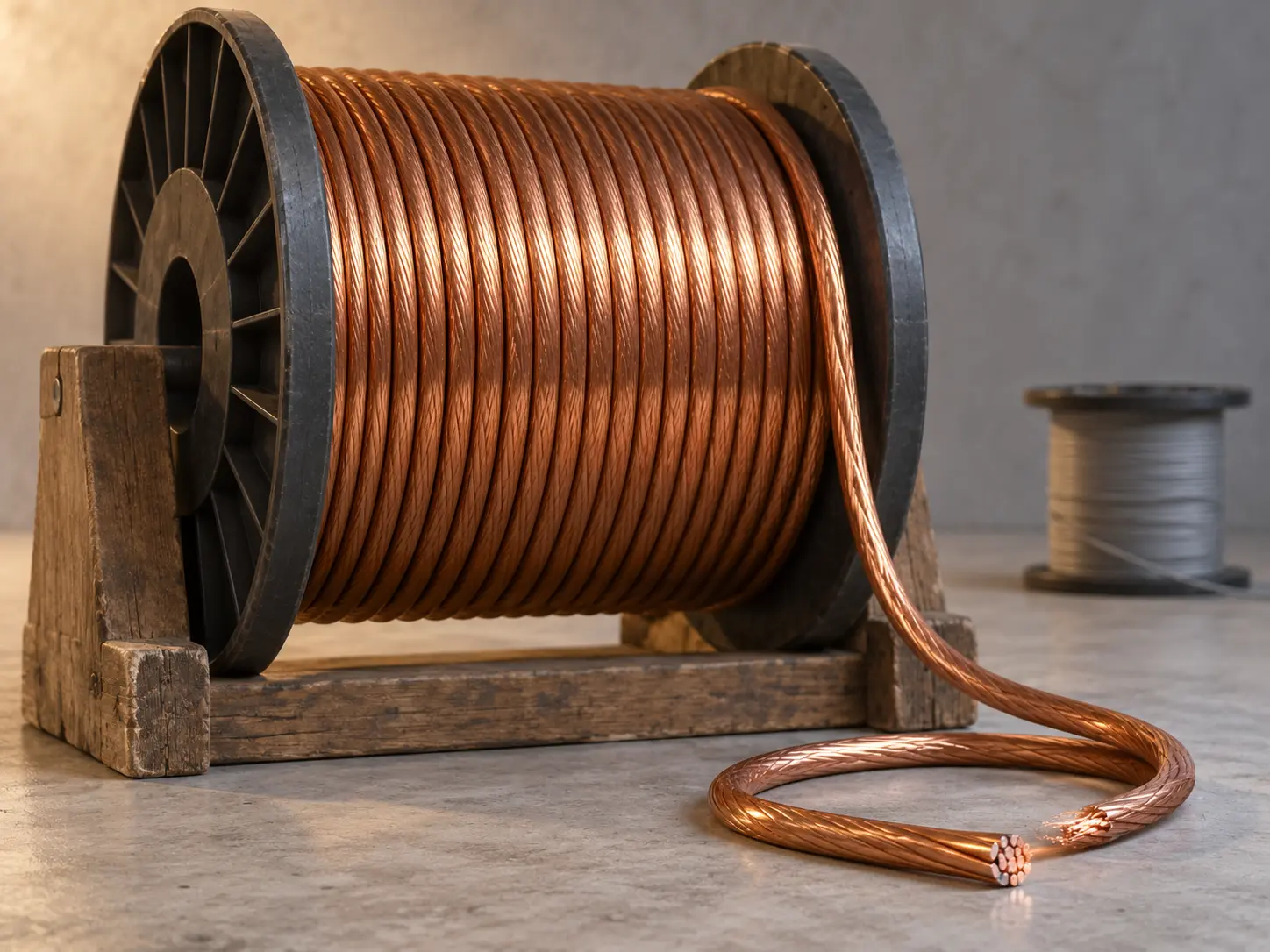
UL 3239 High-Strength Copper HV DC Wire Overview
UL AWM Style 3239 separately permits a 24–10 AWG solid or stranded coated high-strength copper conductor, minimum 90% conductivity, alongside its standard copper or nickel conductor option. This page focuses on that specific conductor construction for protected internal high-voltage DC wiring in inverter and power-conversion equipment.
The Style also carries a maximum 200°C and a maximum 60,000 Vdc, with Horizontal Flame and VW-1 Flame. Those are Style-level ceilings. Choosing the high-strength copper conductor option does not by itself set the temperature or voltage rating of a given construction — the qualified construction record does.
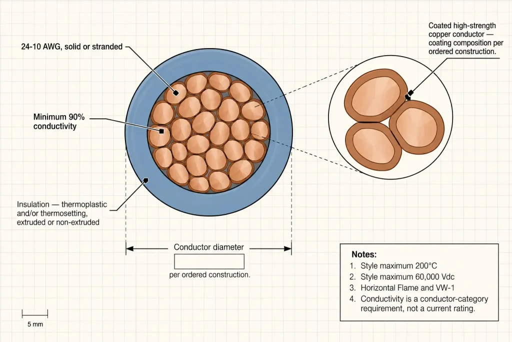
UL 3239 Style-Level Technical Specifications
| Parameter | Style-level information |
|---|---|
| UL AWM Style | 3239 (UL 758) |
| Description | High voltage DC wire with extruded or non-extruded insulation |
| Maximum temperature | 200°C maximum |
| Maximum voltage | 60,000 Vdc maximum |
| Flame | Horizontal Flame and VW-1 |
| Standard copper / nickel range | 24–10 AWG |
| High-strength copper range | 24–10 AWG |
| High-strength copper form | Solid or stranded |
| High-strength copper conductivity | Minimum 90% |
| Aluminum range | 12–10 AWG |
| Resistance wire range | 27–20 AWG |
| Insulation | Thermoplastic and/or thermosetting, extruded or non-extruded |
| Shield | Optional |
| Covering | Optional |
| Jacket | Optional |
| Official Use | Internal wiring of TV receivers or where the acceptability has been determined by Underwriters Laboratories |
What Coated High-Strength Copper Means in the UL3239 File
What the Style establishes is precise and limited: 24–10 AWG, solid or stranded, coated, high-strength copper, minimum 90% conductivity. That is the full technical content of the entry.
What it does not establish is equally worth stating plainly: the exact coating material, tensile strength, strand count, strand diameter, conductor OD and conductor resistance are not part of the Style-level description. None of those are filled in here. Where the drawing controls any of them, they belong in the RFQ as separate line items.
Minimum 90% Conductivity Is a Conductor Requirement
Minimum 90% conductivity describes the conductor category the Style permits — it is part of the specification for the conductor itself, not a derived electrical outcome. It should not be translated into current rating, ampacity, heat generation, power rating or efficiency; those require additional engineering data this page does not supply.
If the buyer’s BOM controls a specific resistance value rather than the conductivity percentage, that resistance limit should be requested separately and confirmed against the ordered construction.
High-Strength Copper vs Standard Copper Conductor
Style 3239 lists a standard 24–10 AWG copper or nickel conductor and, separately, the 24–10 AWG coated high-strength copper option. Both are real, distinct entries in the same Style — this is a construction choice, not a tiered upgrade. Neither is described here as universally “better”; the correct choice depends on the approved drawing or BOM, and no mechanical comparison beyond what the Style states is offered.
High-Strength Copper vs Nickel-Plated Copper
Coated high-strength copper is not automatically the same thing as nickel-plated copper. The Style permits copper conductors to be tinned, silver plated, nickel plated, heat bonded or overcoated as separate finish options, distinct from the high-strength copper conductor category itself. If a drawing specifically requires nickel plating, that is a separate conductor-finish requirement and should be stated as such rather than assumed to be included in a high-strength copper order.
Selecting 24–10 AWG for an Inverter Internal Lead
24–10 AWG is the Style-permitted range for this conductor category, not a recommendation for any particular inverter design. Which size a given internal lead needs is set by the equipment’s engineering data. No AWG-to-ampacity table, current recommendation, or inverter power/kW/HP guidance is published here — those fall outside what the Style establishes.
Why 60,000 Vdc Must Not Be Treated as the Product Rating
60,000 Vdc is the Style maximum, not a rating every high-strength copper construction carries. Terms like “guaranteed 60kV,” “60kV inverter wire” or “60kV high-strength copper SKU” should not be used without construction-specific evidence — the actual ordered construction is what confirms the voltage class, and that confirmation is what belongs in the BOM.
Keep DC and AC Ratings Separate
60,000 Vdc is a DC figure. It should not be restated as 60 kVac, an equivalent AC voltage, a peak AC voltage, a dielectric test voltage, or an impulse rating — the Style maximum is explicitly DC, and none of those AC or test-related figures follow from it.
Maximum 200°C Is Also Construction-Dependent
200°C is a Style ceiling, not an automatic property of the high-strength copper conductor category. Choosing this conductor option does not itself create 200°C capability; the actual ordered temperature rating must be confirmed against the specific construction record, the same as with any other UL 3239 conductor option.
Insulation Must Be Specified Independently
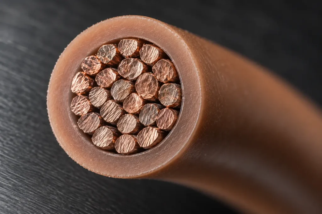
Conductor type does not determine insulation material. Style 3239 permits construction-dependent thermoplastic and/or thermosetting insulation, extruded or non-extruded, regardless of which permitted conductor category is used. If the inverter BOM calls for silicone, XLPE or another permitted insulation system, that material must be verified separately against the qualified construction — it is not assigned automatically by selecting the high-strength copper conductor.
Optional Shield, Covering and Jacket Are Separate Decisions
Style 3239 separately permits an optional shield, an optional covering and an optional jacket. None of these is implied by, or bundled with, a high-strength copper conductor requirement. On this page they are RFQ fields only — state yes or no for each, with specification details where controlled.
Inverter Internal Wiring Does Not Define Voltage or Current
“Inverter” describes an equipment category, not one electrical specification. DC bus voltage, internal lead voltage, conductor-size requirement, temperature requirement and dimensional envelope can all differ materially between inverter designs. Actual engineering requirements have to be supplied by the buyer; no typical inverter voltage is assumed or published here.
Do Not Infer VFD or PWM Performance
UL 3239’s high-voltage DC rating does not by itself establish suitability for repetitive PWM stress, VFD motor outputs, partial-discharge environments, high-frequency common-mode voltage, or shielded drive-cable function. Where any of those characteristics is required, it must be supported by separate technical documentation for the specific construction — this page and the underlying Style entry do not provide it.
Finished OD and Routing Requirements
The Style-level data does not establish one universal finished OD for a high-strength copper construction. Where the inverter enclosure has a controlled routing envelope, request nominal OD, maximum OD, tolerance, routing-channel dimensions and a bend-radius requirement if one is controlled. None of these figures are invented here.
Termination and Connector Requirements
Compatibility with ring terminals, lugs, crimp contacts, HV connectors, busbar terminals or boots is not assumed. Where termination matters, request the terminal part number, connector drawing, strip length, crimp specification and cut length — generic termination settings are not published on this page.
Official AWM Use Boundary
The official Use for Style 3239 is: Internal wiring of TV receivers or where the acceptability has been determined by Underwriters Laboratories.
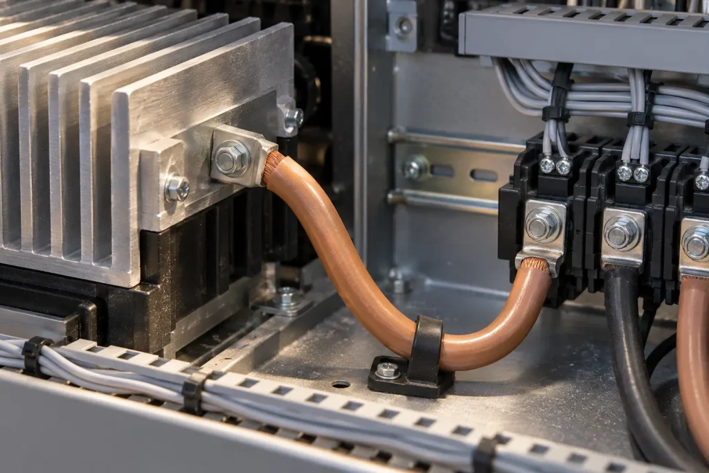
Inverter internal high-voltage DC wiring is the buyer context for this page, distinct from that official Use statement. A buyer may evaluate an appropriate Style 3239 construction for a protected internal high-voltage DC section of inverter or power-conversion equipment where the end-product design and applicable acceptability requirements permit it. This remains an AWM internal-wiring Style — not building wire, field wiring, tray cable, conduit cable, external motor cable, branch-circuit wiring or portable cord.
What Style 3239 Does Not Automatically Define
- Exact voltage rating and exact temperature rating
- Exact coating material and conductor resistance
- Strand count, strand diameter and conductor OD
- Insulation material and insulation thickness
- Finished OD
- Ampacity and current capacity
- Mechanical tensile strength and flex-cycle performance
- Bend radius
- PWM suitability, partial-discharge resistance and VFD suitability
- Terminal compatibility
- Stock, MOQ, reel length and lead time
Common RFQ Mismatches
- “High-strength copper” requested without a coating specified. The Style does not fix one coating material.
- UL3239 requested, actual DC voltage omitted. The construction cannot be confirmed against nothing.
- 60kV / 200°C assumed for every construction. Both are Style ceilings, not defaults.
- High-strength copper assumed to mean nickel-plated copper. They are separate Style entries.
- Inverter use stated, no conductor AWG given. The equipment category does not supply a size.
- VFD / PWM capability expected without a stated technical requirement. Not established by this Style entry.
- Insulation material omitted. Insulation is construction-dependent, not conductor-dependent.
- Maximum OD omitted; terminal specification not provided. Both are needed to confirm fit and termination.
RFQ Checklist
- UL AWM Style 3239
- Coated high-strength copper required: yes
- Conductor AWG within 24–10 AWG
- Solid or stranded
- Required coating, if specifically controlled
- Conductivity requirement
- Actual required DC voltage
- Actual required temperature
- Insulation system, if controlled
- Shield required: yes / no
- Covering required: yes / no
- Jacket required: yes / no
- Nominal / maximum OD
- Color
- Bend-radius limit, if controlled
- Terminal / connector details
- Cut length or reel requirement
- Quantity, packaging and destination
- Documentation requirement
- Actual inverter / power-conversion internal-wiring context
Applicable RoHS / REACH documentation can be confirmed according to the ordered construction. UL marking is applied according to the confirmed ordered construction, and material is supplied as UL-recognized component wire under qualified manufacturing scope.