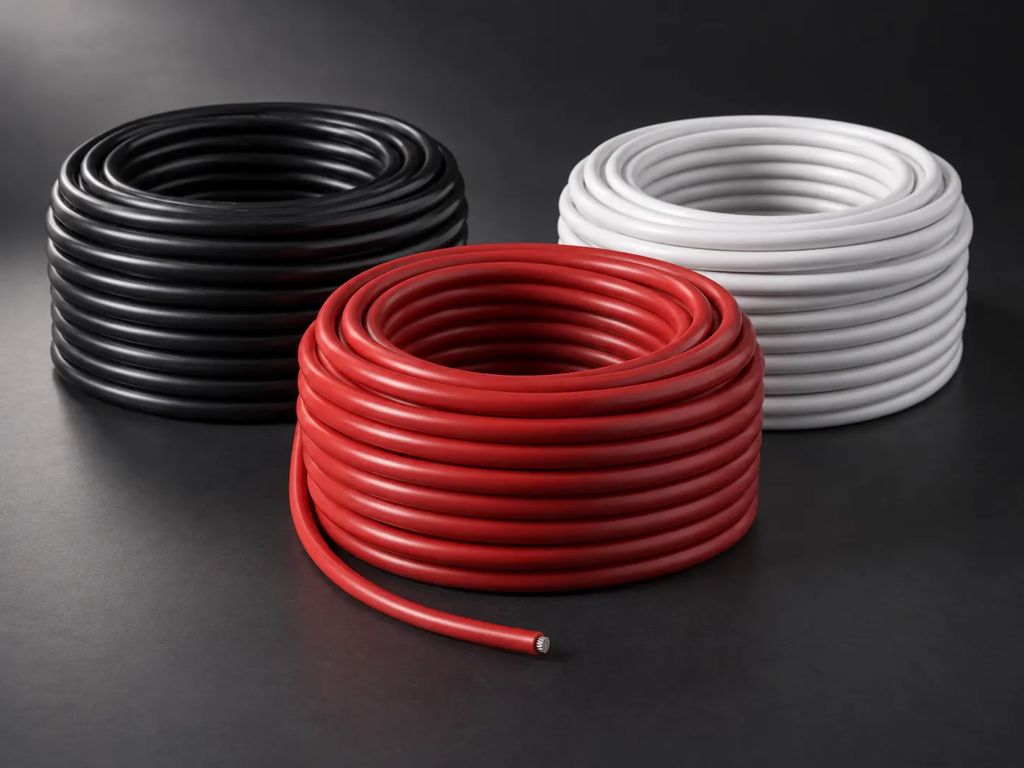
UL 3271 10 AWG XLPE Motor Lead Wire
UL AWM Style 3271 10 AWG XLPE wire, rated 125°C, 600 Vac and 750 Vdc, is a specific conductor-size configuration within Style 3271’s broader 30 AWG–2000 kcmil range, used as a motor lead or for internal wiring of appliances. This page focuses on the 10 AWG SKU — its confirmed XLPE insulation requirement, optional semi-conductive layer, and application boundary — as a defined motor-lead component. 10 AWG represents this page’s specific SKU; it is not presented as universally correct for every motor design. Actual conductor size must follow your motor’s electrical design, equipment drawing, and BOM.
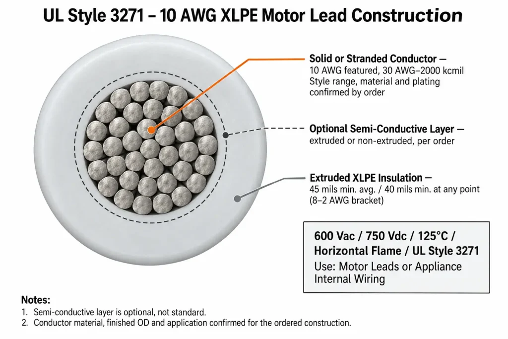
The Confirmed UL 3271 10 AWG Construction
| Parameter | UL 3271 |
|---|---|
| UL AWM Style | 3271 |
| Description | Single conductor with extruded insulation |
| Featured Conductor Size | 10 AWG |
| Style Conductor Range | 30 AWG – 2000 kcmil, solid or stranded |
| Temperature Rating | 125°C |
| Voltage Rating | 600 Vac / 750 Vdc |
| Flame | Horizontal flame |
| Insulation | Extruded XLPE, 45 mils min. average / 40 mils min. at any point (8–2 AWG group) |
| Optional Layer | Extruded or non-extruded semi-conductive polymeric layer over conductor |
| Marking | General; tags may optionally indicate 2500 V peak — for electronic use only |
| UL-Defined Use | Motor leads or internal wiring of appliances |
45/40 Mil XLPE Insulation at 10 AWG
10 AWG falls within UL 3271’s 8–2 AWG insulation-wall bracket, which specifies a minimum average XLPE thickness of 45 mils and a minimum thickness of 40 mils at any point. This is distinct from the Style’s other brackets covering finer or larger conductors, and this page uses only the values applicable to the featured 10 AWG size. This page does not convert this figure into an invented finished outside diameter; conductor geometry, including finished OD, is order-specific.
Optional Semi-Conductive Layer
UL Style 3271 permits an optional extruded or non-extruded semi-conductive polymeric layer over the conductor. This is an order-specific, optional feature — not a default component of every UL 3271 10 AWG wire. This page does not assume the semi-conductive layer is included unless specifically required. If your motor design requires this layer, state it explicitly in your RFQ.
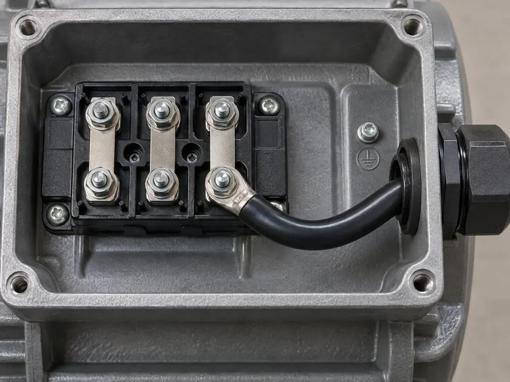
Motor Leads or Appliance Internal Wiring — Not General Inverter/Drive Wiring
This distinction matters for accurate specification. UL Style 3271’s confirmed Use is motor leads or internal wiring of appliances — it is not defined by UL as general inverter internal wiring, drive-system wiring, or industrial power-control equipment wiring in a broader sense. Where a motor lead genuinely connects motor terminals within an inverter-driven or drive-controlled system, that falls within the confirmed motor-lead use; but this page does not extend UL 3271 into a general “industrial power control” or “inverter/drive internal wiring” positioning beyond that specific motor-lead application.
10 AWG Does Not Establish Current-Carrying Capacity
This page does not publish a generic ampacity figure simply because the product is 10 AWG, and does not infer allowable current from the 10 AWG conductor size or the 600 Vac / 750 Vdc voltage ratings — these are separate parameters. Current-carrying suitability for a motor lead depends on the actual conductor construction, motor design, ambient conditions, and installation, and must be evaluated accordingly rather than assumed from AWG alone.
600 Vac and 750 Vdc Are Not Automatically Your Motor’s Operating Voltage or DC-Bus Design
UL 3271’s 600 Vac and 750 Vdc figures are the Style’s rated voltage limits — they are not automatically equal to your motor’s actual operating voltage or your drive system’s DC-bus voltage. If your project involves a VFD-driven motor or a specific DC-bus design, confirm your actual circuit voltage and any VFD-specific insulation requirement separately; this page does not make VFD-specific performance claims beyond the confirmed Style rating.
Conductor Form, Material, Termination and Connectors: RFQ Fields
UL Style 3271 permits solid or stranded conductor construction at 10 AWG; conductor material and plating are not established by the Style data. This page does not describe UL 3271 10 AWG as a fixed bare-copper or tinned-copper product — if your BOM or drawing specifies a conductor material, plating, terminal, connector, or termination process for the motor lead, include that in your RFQ so the corresponding construction can be confirmed.
Common RFQ Gaps for UL 3271 10 AWG Motor Leads
Certain specification fields are frequently left out of an initial enquiry and typically require a follow-up before an accurate quotation can be issued. These are common information gaps, not observations about any particular buyer: UL 3271 and 10 AWG are stated but conductor form is omitted; conductor plating required by terminal design is not stated; maximum OD is omitted; a buyer requests “VFD motor wire” without defining VFD-specific requirements; 600 Vac is confused with the actual motor operating voltage; 750 Vdc is confused with the DC-bus design; the optional semi-conductive layer is not clearly specified; terminal information is missing; a cut length is provided without a tolerance; or quantity is provided without a packaging method. Resolving these items reduces quotation revisions and construction mismatch.
What UL 3271 Does Not Automatically Define
The Style data does not automatically define: conductor material, conductor plating, strand count, strand diameter, conductor resistance, ampacity, current rating, motor operating voltage, DC-bus voltage, finished OD, bend radius, flex-cycle rating, terminal compatibility, connector compatibility, standard colour, cut-length tolerance, reel length, MOQ, stock, lead time, or production capacity. These remain RFQ, drawing, or ordered-construction parameters where relevant.

RFQ Checklist for UL 3271 10 AWG XLPE Motor Lead Wire
To request an accurate quotation, please provide:
- UL AWM Style 3271
- 10 AWG
- Solid or stranded
- Conductor material, if controlled
- Conductor plating, if controlled
- 125°C requirement
- 600 Vac requirement
- 750 Vdc requirement
- Motor-lead application
- Optional semi-conductive layer required or not required
- Insulation colour
- Nominal or maximum finished OD, if controlled
- Terminal / contact type
- Connector information
- Termination method
- Cut length, if applicable
- Quantity
- Reel or packaging requirement
- Destination
- Documentation requirements
Applicable RoHS / REACH documentation can be confirmed according to the ordered construction.
See the UL 3271 XLPE Wire category, our XLPE Wire range, or our AWM Wire category for other conductor sizes within this Style.