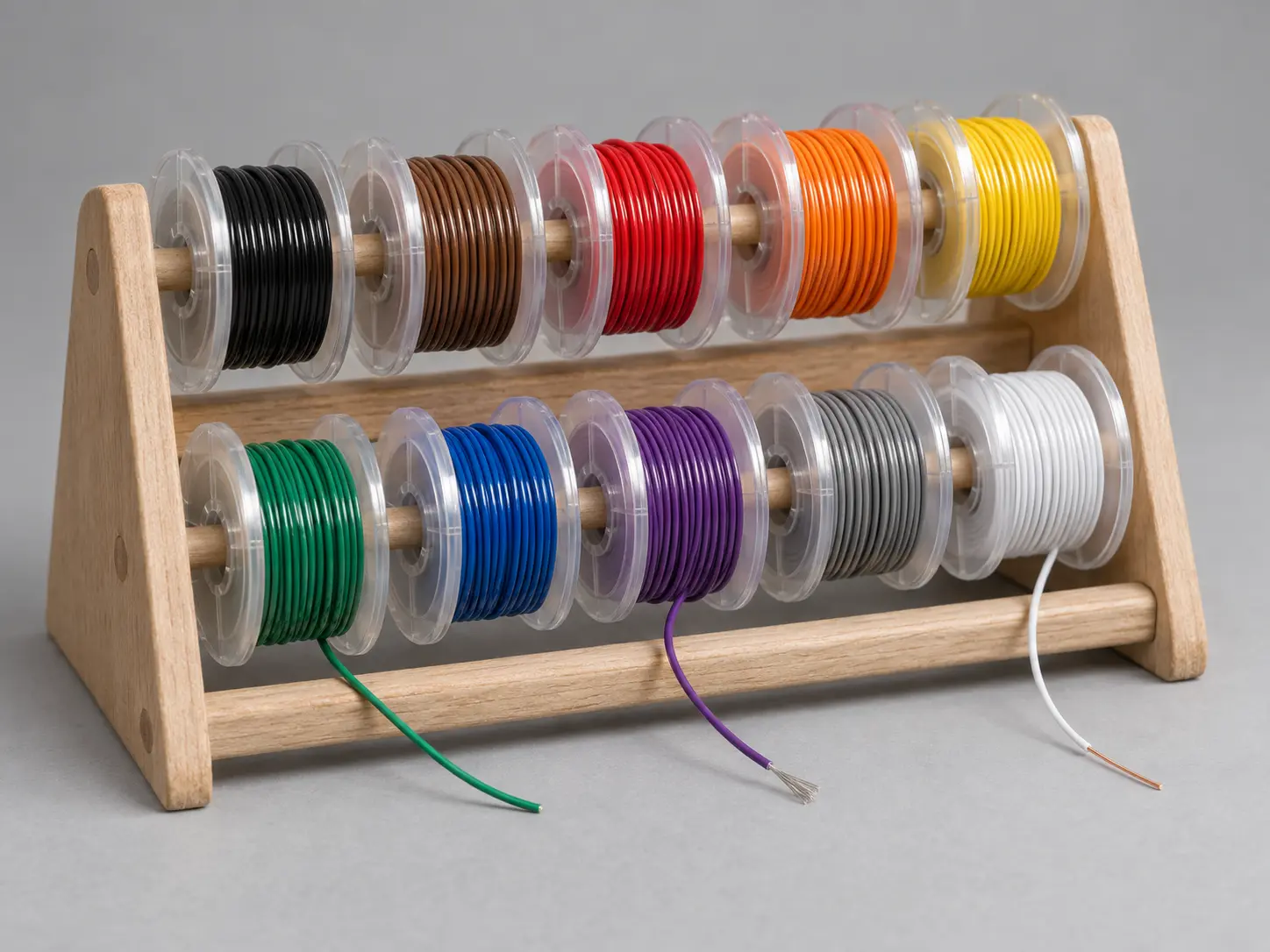
UL 1569 for Fixed Internal Wiring of Electronic Equipment
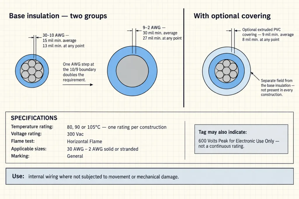
UL AWM Style 1569 is a single conductor with extruded PVC insulation, rated 300 Vac with Horizontal Flame, in 80°C, 90°C or 105°C temperature ratings. The Style conductor range is 30 AWG through 2 AWG, solid or stranded.
The official Use reads: internal wiring of appliances or electronic equipment where not subjected to movement or mechanical damage. This page addresses the electronic-equipment branch of that Use, and it keeps the condition attached — the wire is for fixed, protected internal positions.
The page focuses on the 30–10 AWG subset, where the Style specifies 15 mils minimum average insulation with 13 mils minimum at any point. That is the thin-wall group. The rest of the Style is not thin-wall, and the section below explains why the distinction matters at RFQ stage.
Verified UL Style 1569 Construction
| Parameter | Style-level information |
|---|---|
| UL AWM Style | 1569 |
| Construction | Single conductor with extruded insulation |
| Temperature rating | 80°C, 90°C or 105°C |
| Voltage rating | 300 Vac |
| Flame | Horizontal Flame |
| Conductor range | 30 AWG–2 AWG |
| Conductor form | Solid or Stranded |
| Insulation | Extruded PVC |
| 30–10 AWG insulation | 15 mil average / 13 mil minimum at any point |
| 9–2 AWG insulation | 30 mil average / 27 mil minimum at any point |
| Optional covering | Extruded PVC, 9 mil average / 8 mil minimum at any point |
| Marking | General |
| Official Use | Internal wiring of appliances or electronic equipment where not subjected to movement or mechanical damage |
| Optional tag — not a normal rating | 600 Volts Peak for Electronic Use Only |
This page’s procurement subset: 30–10 AWG with the 15 mil base insulation.
“Thin-Wall” Applies to One Group, Not the Style
Style 1569 contains two base-insulation groups, and they differ by a factor of two.
From 30 AWG through 10 AWG the requirement is 15 mils minimum average with 13 mils minimum at any point. From 9 AWG through 2 AWG it doubles to 30 mils minimum average with 27 mils minimum at any point. The Style does not end at 10 AWG; it continues through 2 AWG on the thicker requirement.
So “thin-wall” is used on this page as a descriptive term for the 30–10 AWG group only. It is not the formal UL title of Style 1569, and it is not accurate to say that all Style 1569 wire is 15 mil, that the Style universally means thin-wall PVC, or that 30 AWG through 2 AWG share one wall.
The practical consequence: a design stepping from 10 AWG to 9 AWG crosses the group boundary, and the base insulation requirement doubles. That is a construction change hidden behind a single size step on a BOM.
Three Temperature Options, One Confirmed Rating
Style 1569 includes 80°C, 90°C and 105°C rating possibilities. These are alternatives permitted by the Style, not three ratings a single wire carries at once.
The required temperature rating should be specified during RFQ and confirmed against the ordered construction. Nothing here advertises every order as 105°C, describes 105°C as standard, or presents it as applying to every Style 1569 construction.
300 Vac Is the Normal Rating
The normal Style voltage rating is 300 Vac, and it is used precisely here. Style 1569 is not described as 600V wire, 600 Vac wire, 300/600V wire or 600V PVC hook-up wire.
The 600 Volts Peak Tag Is Separate
The Style permits a tag indicating “600 Volts Peak for Electronic Use Only.” This is not the normal continuous voltage rating, and the two are kept apart:
Normal Style rating: 300 Vac.
Optional tag: 600 Volts Peak for Electronic Use Only.
The tag is not restated here as 600 Vac, 600V continuous, “UL1569 600V wire”, 300/600V wire or 600V appliance wire. Where a design references the peak notation, whether the ordered construction qualifies and whether the application matches “for electronic use only” are both confirmed against that construction.
Not Subjected to Movement or Mechanical Damage
This condition is part of the Use sentence, and it is broader than a repeated-flexing restriction. The wording excludes movement, not merely repeated flexing, and it separately excludes exposure to mechanical damage.
Style 1569 is therefore not positioned here for continuous flexing, robotic movement, drag-chain use, moving machine parts, hinged repeated-motion wiring, external abrasion exposure or unprotected mechanical routing. No flex-cycle performance, bend-life rating, abrasion rating or dynamic-flex classification is published, because the Style record establishes none.
Where a lead position involves movement during operation or service, or where the wire would be exposed to mechanical damage, the application falls outside this Use and needs a different evaluation. Stating the movement and protection conditions in the enquiry is the fastest way to establish whether Style 1569 fits at all.
Fixed Internal Electronic-Equipment Wiring
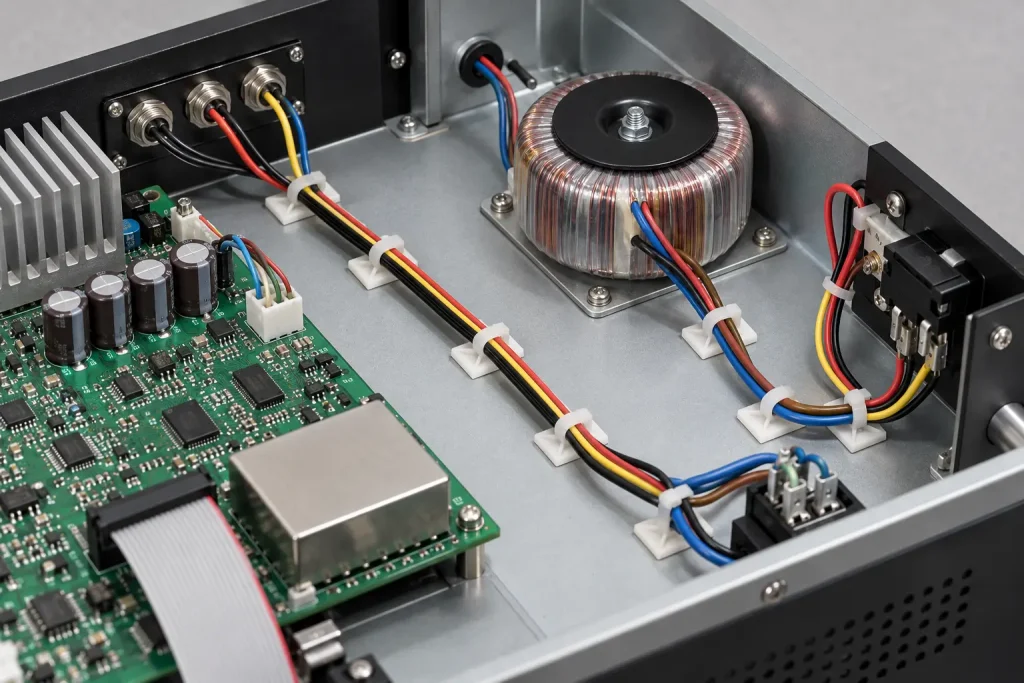
The practical contexts on this page are fixed and internal: component-to-component leads inside an enclosure, protected internal electronic-equipment wiring, internal wire paths within the housing, connections between electrical or electronic subassemblies, and drawing-controlled fixed internal leads.
The Use does not extend to unrestricted industrial equipment wiring, machine wiring, automation wiring, control-panel field wiring, building wiring, branch circuits, tray, conduit, raceway, portable cord or an external equipment supply cord.
OEM Is a Buyer Context, Not a Use
OEM describes who is buying, not what the Style covers. A buyer being an OEM does not itself determine whether Style 1569 is appropriate for a given lead.
What determines it is the official Use: internal wiring of electronic equipment where not subjected to movement or mechanical damage. Application claims on this page stay anchored to that sentence, and Style 1569 is not described as generally approved for all OEM equipment.
The Optional PVC Covering
Style 1569 permits an optional extruded PVC covering at 9 mils minimum average thickness with 8 mils minimum at any point.
This is a separate construction field from the base insulation, with its own requirement, and it is optional. Not every Style 1569 wire includes it. It is not described here as mandatory, as making the product jacketed or double-insulated by default, or as providing abrasion protection, mechanical reinforcement or additional flame protection — none of those performance characteristics is established by the Style information.
Where the covering is required, it is confirmed as part of the ordered construction and stated in the enquiry.
Conductor Requirements
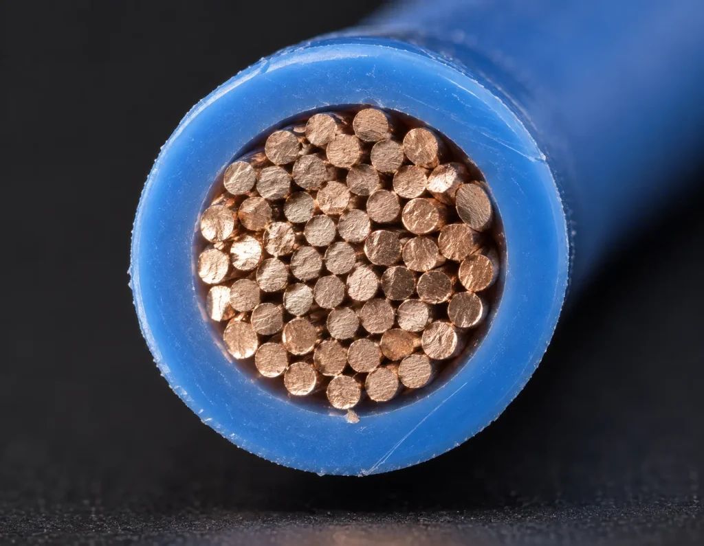
Official Style 1569 defines the 30 AWG–2 AWG range and the solid or stranded form. It defines nothing else about the conductor.
Copper, tinned copper, bare copper, silver-plated copper and nickel-plated copper are none of them established at Style level, and no strand count, strand diameter, conductor diameter, lay length, conductor resistance or ampacity is stated here. Where a buyer needs a specific material, finish or strand construction, each is an RFQ confirmation item.
Finished OD
No universal finished outside diameter is published. The Style specifies minimum insulation thickness, not a fixed finished diameter.
Finished OD depends on the conductor size, the solid or stranded construction, the detailed conductor construction, the base insulation dimensions, and whether the optional PVC covering is included.
The 15 mil base-insulation group is accurately described as the thin-wall focus of this page. That is a statement about the insulation requirement, not a claim of smallest OD, ultra-compact wire, space-saving final diameter or a guaranteed compact finished profile. Where a dimensional constraint exists, request the required AWG, the maximum finished OD, the OD tolerance, the routing clearance and connector cavity dimensions where applicable.
Bulk Wire and a Processed Lead
Style 1569 defines single-conductor wire. It does not define cut length, strip length, terminal, connector, crimp, ferrule, wire seal, a finished lead or a completed harness.
Where processed leads are required, those requirements are separately specified and confirmed. Cutting, stripping, crimping and harness assembly are not presented here as automatically included.
What Style 1569 Does Not Define
- Conductor material and conductor plating
- Strand count, strand diameter and conductor resistance
- Ampacity
- Finished OD and OD tolerance
- Colour
- Terminal, connector, cut length and strip length
- Reel length, MOQ, stock and lead time
Each requires customer specifications, verified SKU documentation, ordered-construction confirmation or separate commercial confirmation.
Common Procurement Errors
- 15 mil insulation assumed for every size. It applies to 30–10 AWG only.
- 9–2 AWG called a 15 mil thin-wall construction. That group requires 30 mil average.
- Style 1569 assumed to be universally 105°C. The Style permits 80, 90 or 105°C.
- “600 Volts Peak for Electronic Use Only” treated as a normal 600 Vac rating. The rating is 300 Vac.
- Requested with no AWG. Two insulation groups sit inside the range.
- Stranded tinned copper assumed. Conductor material is not set at Style level.
- Optional PVC covering assumed to be standard. It is confirmed per construction.
- One universal finished OD assumed. OD depends on size, construction and covering.
- Used in a continuously moving application. The Use excludes movement.
- Used where the wire is exposed to mechanical damage. The Use excludes that too.
- Fixed internal electronic-equipment wire confused with external supply or building wire.
RFQ Checklist
- UL AWM Style 1569 requirement
- Required conductor size
- Whether the request falls within the 30–10 AWG thin-wall subset
- Solid or stranded requirement
- Required conductor material
- Required conductor finish or plating
- Detailed stranding, if controlled
- Required temperature rating — 80°C, 90°C or 105°C
- Insulation colour
- Optional PVC covering required: yes / no
- Maximum finished OD, if controlled
- Electronic equipment type
- Internal installation location
- Confirmation that the wire is not subjected to movement or mechanical damage
- 300 Vac circuit requirement
- Whether the optional 600 Volts Peak for Electronic Use Only tag is relevant
- Customer drawing
- Existing wire specification
- Cut length, if applicable
- Strip length
- Terminal or connector requirements
- Marking requirement
- Quantity
- Packaging
- Destination
- Required compliance documentation
These are RFQ inputs. No combination is presented as automatically available.
Substitution
Different UL AWM Styles have their own ratings, conductor ranges, insulation requirements, coverings and Uses. No Style is presented here as automatically becoming the correct alternative on the basis of conductor size or voltage alone, and none is treated as interchangeable with Style 1569.
Any substitution is checked against the actual equipment specification, including the movement and mechanical-damage condition that applies to this Style’s Use.
UL Marking and Documentation
Material is supplied as UL-recognized component wire where supplied under qualified manufacturing scope, and UL marking is applied according to the confirmed ordered construction. The Style-level marking designation is General.
CSA AWM, FT1, VW-1 and dual UL / CSA certification are not claimed here; any additional certification depends on the ordered construction. Applicable RoHS / REACH documentation can be confirmed according to the ordered construction.
Flame Classification
The verified Style-level designation is Horizontal Flame. VW-1 and FT1 are separate classifications and are not claimed here; Horizontal Flame is not converted into either. Any separately confirmed vertical-flame construction remains order-specific.