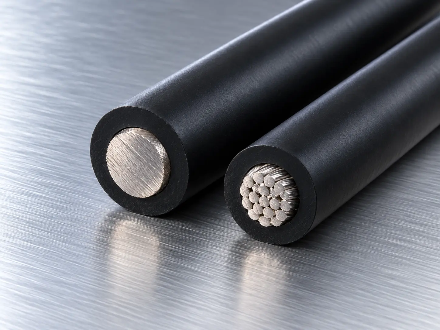
UL 3321 3–2 AWG XLPE Wire for Appliance Internal Wiring
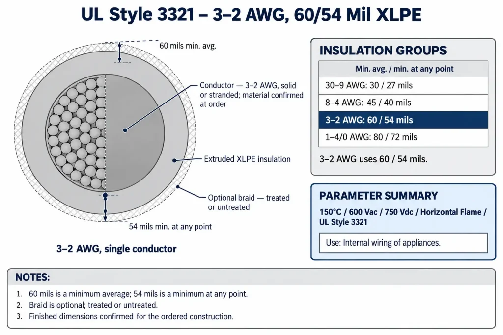
UL AWM Style 3321 is a single conductor with extruded insulation, rated 150°C, 600 Vac and 750 Vdc with a Horizontal flame classification. Its insulation is extruded XLPE (cross-linked polyethylene), with wall requirements set by conductor-size group. For 3 AWG and 2 AWG, the Style requires a minimum average wall of 60 mils and a minimum of 54 mils at any point. The Use is “Internal wiring of appliances.”
This page covers that 3–2 AWG construction: what the two wall requirements mean, where the group sits in the Style’s schedule, the optional braid, and what an RFQ should state. For the broader Style overview, see the UL 3321 XLPE Wire category.
Verified UL 3321 Technical Specifications
| Parameter | UL AWM Style 3321 record |
|---|---|
| Style | 3321 |
| Description | Single conductor with extruded insulation |
| Temperature | 150°C |
| AC voltage | 600 Vac |
| DC voltage | 750 Vdc |
| Flame | Horizontal flame |
| Full conductor range | 30 AWG – 4/0 AWG |
| Conductor form | Solid or stranded |
| Insulation | Extruded XLPE |
| Wall, 3 – 2 AWG | 60 mils (1.52 mm) minimum average; 54 mils (1.37 mm) minimum at any point |
| Covering | Optional, treated or untreated braid |
| Marking | General |
| Use | Internal wiring of appliances |
Four points in this table need clarification. First, the millimetre values are arithmetic conversions (1 mil = 0.0254 mm), not separate UL specifications. Second, 600 Vac and 750 Vdc are two separate ratings, one AC and one DC; they are not a combined AC/DC figure. Third, the braid is optional, so a construction may be supplied with or without it. Fourth, the record does not state the conductor material or plating; these are confirmed according to the qualified ordered construction.
3–2 AWG, 60/54 Mil XLPE Construction
For 3 AWG and 2 AWG, the extruded XLPE wall must meet two separate requirements:
- 60 mils minimum average: the average of wall-thickness measurements around the insulation must not fall below 60 mils.
- 54 mils minimum at any point: the thinnest point anywhere in the wall must not fall below 54 mils.
A qualified construction must meet both. A wall averaging above 60 mils still fails if one point measures below 54 mils, and a wall with no point below 54 mils still fails if its average is below 60 mils. 60 mils is a minimum average, not a nominal or exact wall; 54 mils is a minimum at any point, not an average. The 6-mil difference is not a tolerance band. The actual wall of an ordered construction may exceed 60 mils.
The finished outside diameter is not calculated from conductor size and these values, and no total finished diameter is guaranteed. Where a drawing controls finished diameter or tolerance, it is confirmed against the ordered construction.
Both 3 AWG and 2 AWG may be solid or stranded at Style level. The record does not define strand count, strand diameter, conductor class, lay length or resistance, and it assigns no current rating to either size. 3 AWG and 2 AWG are conductor sizes; they do not by themselves describe a high-power, high-current, feeder or main-lead application.
The record identifies the insulation as extruded XLPE without further compound properties. No oil, chemical, abrasion, low-smoke, halogen-free, radiation or weather performance is attributed to it here.
UL 3321 Insulation Thickness by Conductor Size
| Conductor size group | Minimum average thickness | Minimum thickness at any point |
|---|---|---|
| 30 – 9 AWG | 30 mils | 27 mils |
| 8 – 4 AWG | 45 mils | 40 mils |
| 3 – 2 AWG (this page) | 60 mils | 54 mils |
| 1 – 4/0 AWG | 80 mils | 72 mils |
Two points in this table need clarification. First, 3–2 AWG is the shortest group in the schedule, only two sizes, and its values apply to those two sizes alone: 4 AWG uses 45/40 and 1 AWG uses 80/72. Second, every pair is a minimum average and a minimum at any point; none is a nominal wall. The 3–2 AWG group remains the subject of this page.
150°C, 600 Vac and 750 Vdc
The rating field reads “150 deg C, 600 Vac, 750 Vdc, Horizontal flame.”
- 150°C: the rated temperature of the Style. The record does not describe it as continuous-duty or long-term, and no service life or thermal margin is derived from the difference between this rating and any application temperature.
- 600 Vac: the AC voltage rating.
- 750 Vdc: the DC voltage rating, stated separately in the record. It is not an AC value, and the AC rating is not a DC value.
Horizontal flame is the flame classification. VW-1, FT1, FT2 and vertical flame are not Style-wide properties; any additional flame requirement is confirmed separately for the ordered construction.
Optional Treated or Untreated Braid
The covering field reads “Optional, treated or untreated braid.” The braid is optional and is not part of every UL 3321 construction, and the Style permits either a treated or an untreated braid. The record does not name the braid material and does not attribute any abrasion, mechanical, cut, chemical, moisture or flame function to it, so none is claimed here. A braid requirement, including treated or untreated condition and any material the drawing specifies, is stated in the RFQ and confirmed for the qualified ordered construction. The optional braid at 4/0 AWG is covered in more detail on the UL 3321 4/0 AWG optional-braid page.
Appliance Internal Wiring
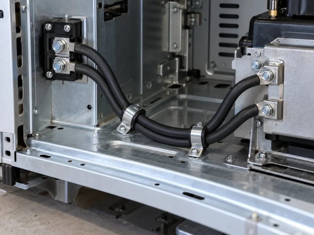
The Use of Style 3321 is “Internal wiring of appliances.” The Style is intended for wiring inside an appliance, where the appliance design specifies Style 3321 and the 150°C, 600 Vac and 750 Vdc ratings and the construction are appropriate.
The larger conductor size of the 3–2 AWG group does not widen this Use. Style 3321 is not building wire, branch-circuit, field, tray or conduit wiring, an external appliance cord, facility wiring or power-distribution cable. The record designates appliance internal wiring only; it does not designate motor leads, and motor-lead wording from other XLPE Styles is not applied here.
Current-carrying capacity is not a Style-level figure. No ampacity, breaker or fuse size, kW, kVA, motor or heater size is given for 3 AWG or 2 AWG, and none is derived from generic AWG tables. Actual current requirements depend on the appliance design and the qualified construction.
What Style 3321 Does and Does Not Define
For 3–2 AWG, the Style record defines the construction (single conductor, extruded insulation); the rating (150°C, 600 Vac, 750 Vdc, Horizontal flame); the conductor form (solid or stranded); the insulation (extruded XLPE) and its 60-mil minimum average and 54-mil minimum-at-any-point wall; the optional treated or untreated braid; the marking field (General); and the Use.
The Style record does not define:
- conductor material, plating or strand construction
- conductor resistance or current rating
- finished outside diameter or tolerance
- braid material or braid performance
- XLPE compound properties beyond the material name
- a vertical flame rating
- bend radius or service life
Common Procurement Errors
- Applying the 45/40 mil values of 8–4 AWG, or the 80/72 values of 1–4/0 AWG, to 3–2 AWG.
- Treating 60 mils as nominal, or 54 mils as an average.
- Calculating finished diameter from the wall values.
- Combining the ratings as “600V AC/DC” or omitting the 750 Vdc rating.
- Assuming every construction includes a braid, or assigning a braid material.
- Assuming a conductor material or plating.
- Assigning a current rating to 3 AWG or 2 AWG.
- Describing the wire as motor-lead, feeder or building wire.
How to Specify UL 3321 3–2 AWG XLPE Wire in an RFQ
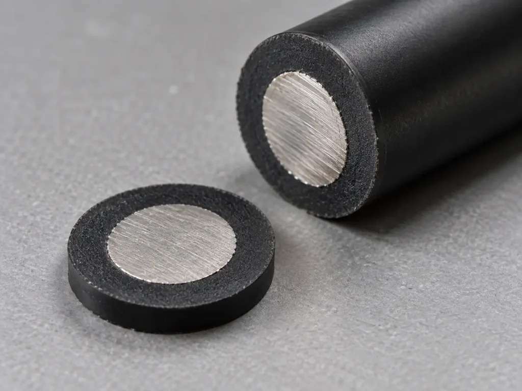
The Style fixes the construction, the ratings, the conductor forms, extruded XLPE, the 60/54 mil wall for 3–2 AWG, the optional braid provision and the Use. The following should be stated by the buyer and confirmed for the ordered qualified construction, not filled with assumed values:
- 3 AWG or 2 AWG
- solid or stranded
- conductor material requirement
- conductor plating requirement
- detailed stranding, if controlled
- 150°C requirement
- 600 Vac and/or 750 Vdc operating requirement
- optional braid requirement
- treated or untreated braid requirement, if controlled
- insulation colour
- finished OD or tolerance, if controlled
- marking requirement
- appliance type
- internal wiring location
- current requirement
- terminal or connector interface
- quantity
- packaging
- required compliance documentation
UL Marking and Documentation
Style 3321 wire is supplied as UL-recognized component wire where supplied under qualified manufacturing scope. The marking field of the Style record reads “General” and does not prescribe a fixed print legend. UL marking is applied according to the confirmed ordered construction, including whether a braid is present, and should be confirmed at the order stage.
Applicable RoHS / REACH documentation can be confirmed according to the ordered construction. CE, UKCA, CSA, FT1, VW-1, CPR, VDE, DIN, EN and IEC are not declared for this product.
Commercial, origin, compliance and transport documents are identified during quotation and confirmed according to the order.