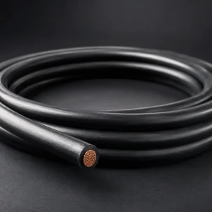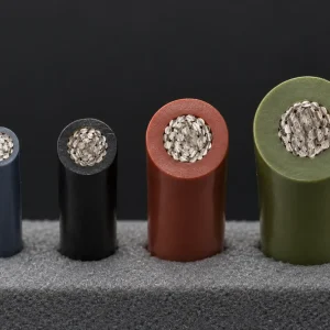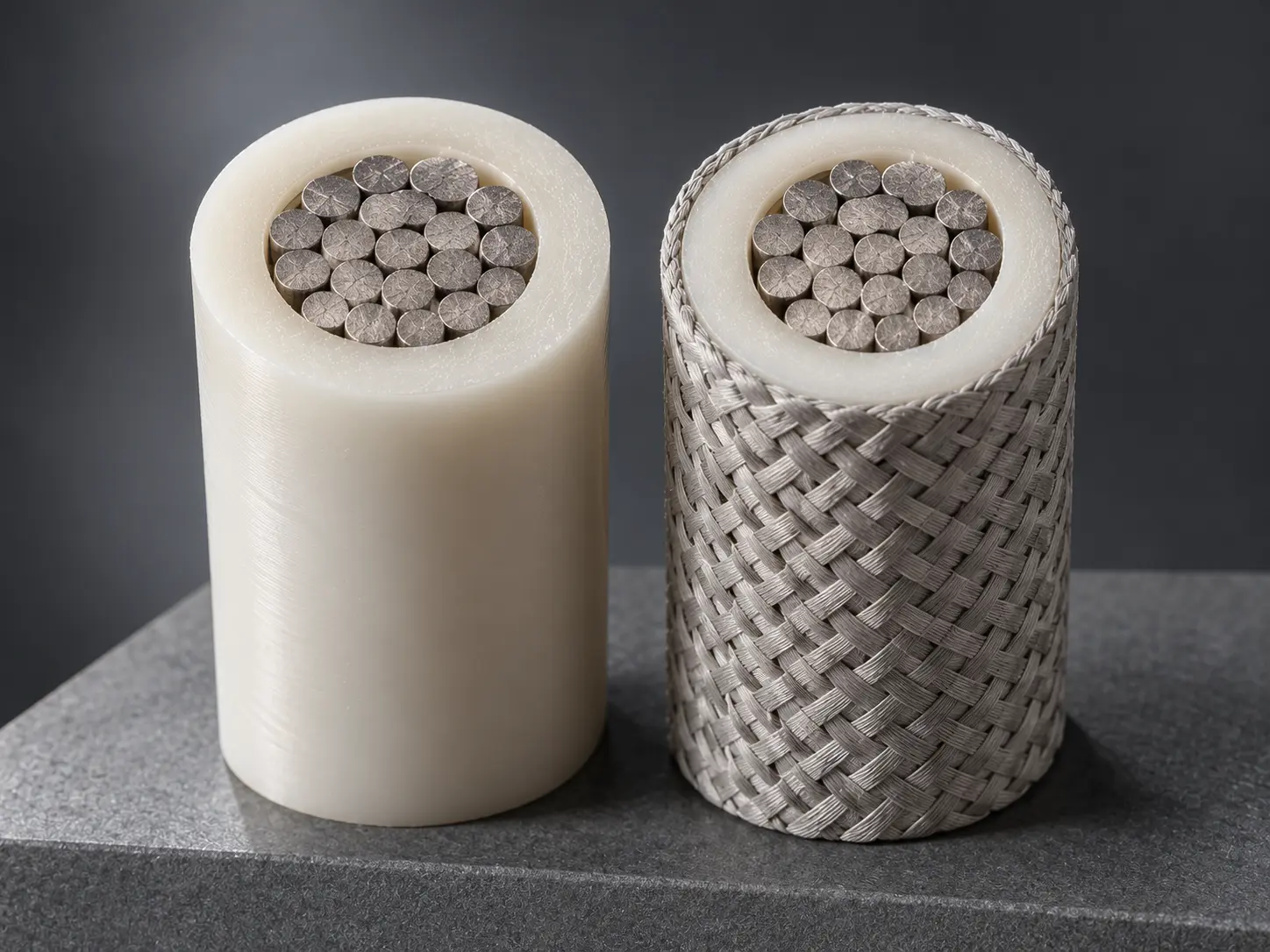
UL 3321 4/0 AWG XLPE Wire with Optional Braid
UL AWM Style 3321 is a single conductor with extruded insulation. Its rating field reads “150 deg C, 600 Vac, 750 Vdc, Horizontal flame.” The Style covers 30 AWG to 4/0 AWG, solid or stranded, with extruded XLPE insulation whose minimum thickness depends on conductor size, and its covering field reads “Optional, treated or untreated braid.” The Use is “Internal wiring of appliances.”
This page covers one construction within that Style: 4/0 AWG, the largest size in the range. It sets out the insulation group that applies to 4/0 AWG, the two thickness requirements of that group, and above all the optional braid: what the Style wording establishes, what it leaves undefined, and how to state a braid requirement in an RFQ. For the broader Style overview and the other constructions offered under it, see the UL 3321 XLPE Wire category.
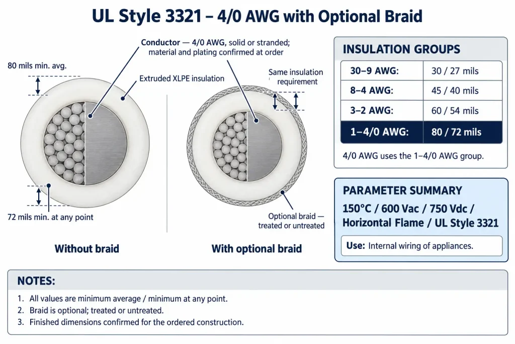
Verified UL 3321 Technical Specifications
| Parameter | UL AWM Style 3321 record |
|---|---|
| Style | 3321 |
| Construction | Single conductor with extruded insulation |
| Page-specific size | 4/0 AWG |
| Style conductor range | 30 AWG – 4/0 AWG |
| Conductor form | Solid or stranded |
| Temperature | 150°C |
| Voltage (AC) | 600 Vac |
| Voltage (DC) | 750 Vdc |
| Flame | Horizontal flame |
| Insulation | Extruded XLPE |
| 4/0 AWG wall group | 1 – 4/0 AWG: 80 mils minimum average, 72 mils minimum at any point |
| Covering | Optional, treated or untreated braid |
| Marking | General |
| Use | Internal wiring of appliances |
Four points in this table need clarification. First, the AC and DC ratings are separate entries, 600 Vac and 750 Vdc; they are not a combined figure and not a single rating for both. Second, the conductor entry defines size range and form only; conductor material, plating, strand construction, conductor area and conductor diameter are confirmed according to the ordered construction. Third, the covering is optional, so a construction may be supplied with or without a braid. Fourth, the insulation values shown apply to 4/0 AWG only; the complete group table for the Style follows below.
4/0 AWG Falls in the 1–4/0 AWG Insulation Group
Style 3321 does not set a single insulation thickness for the whole range. It divides the conductor range into four groups, each with its own pair of minimum values:
| Conductor size group | Minimum average thickness | Minimum thickness at any point |
|---|---|---|
| 30 – 9 AWG | 30 mils | 27 mils |
| 8 – 4 AWG | 45 mils | 40 mils |
| 3 – 2 AWG | 60 mils | 54 mils |
| 1 – 4/0 AWG | 80 mils | 72 mils |
Three points in this table need clarification. First, 4/0 AWG sits in the last group, so its requirement is 80 mils minimum average and 72 mils minimum at any point. Second, the 60/54 mil values belong only to 3–2 AWG and do not apply to 4/0 AWG; likewise the 30/27 and 45/40 mil values apply only to their own groups. Third, the group boundaries are fixed by the record, so values from one group are never carried over to a neighbouring size.
80 Mil Average and 72 Mil Minimum at Any Point
The 1–4/0 AWG group sets two separate requirements for the extruded XLPE wall, and a qualified construction must meet both:
- 80 mils minimum average (2.03 mm by unit conversion): the average of wall-thickness measurements around the insulation must not fall below 80 mils.
- 72 mils minimum at any point (1.83 mm by unit conversion): the thinnest point anywhere in the wall must not fall below 72 mils.
The millimetre figures are arithmetic conversions (1 mil = 0.0254 mm), not separate UL specifications. The two requirements are independent. A wall averaging above 80 mils still fails if one point measures below 72 mils, and a wall with no point below 72 mils still fails if its average is below 80 mils. The 8-mil difference is not a tolerance band, and 80 mils is not a nominal, exact, target or finished wall. The actual wall of an ordered construction may exceed 80 mils.
For the same reason, the finished outside diameter of a 4/0 AWG construction cannot be calculated from generic AWG data plus twice the insulation thickness, and with the optional braid present, a further layer is added to the finished construction. Where the finished diameter matters, it is confirmed against the ordered construction.
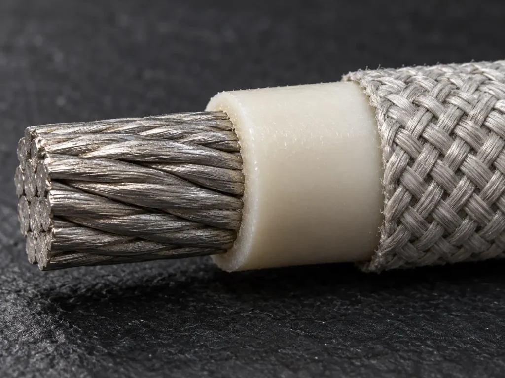
Optional Treated or Untreated Braid
The covering field of Style 3321 reads: “Optional, treated or untreated braid.” That short sentence establishes three things, and only three:
- The braid is optional. Style 3321 constructions may be supplied without a braid. The braid is not part of every construction, and no default is implied.
- A braid, where present, is a covering over the insulation. The Style describes it as a covering; it does not replace or alter the insulation requirement, which stays at 80/72 mils for 4/0 AWG with or without a braid.
- Treated and untreated braids are both permitted. The Style wording allows either condition. It does not prefer one over the other.
What the covering field does not establish is equally important. It does not name the braid material, the treatment material or the braid construction. It does not assign the braid any mechanical, abrasion, cut, thermal, moisture, chemical or flame performance, and it does not state that a braid extends service life. None of these properties can be inferred from the presence of a braid, and this page does not assign any of them.
In practical ordering terms, a 4/0 AWG Style 3321 construction with a braid and one without are different finished constructions. The braid adds a layer that affects finished dimensions, handling at terminations and the marking and documentation for the order. For that reason, an RFQ should state explicitly:
- whether a braid is required, not required, or left open;
- if required, whether it must be treated or untreated, where the drawing specifies this;
- any braid material or construction that the drawing specifies, so it can be confirmed against the ordered qualified construction;
- any finished-diameter limit that must be met with the braid in place.
If a drawing simply says “UL 3321” without addressing the covering, the braid requirement is undefined and should be clarified before quotation rather than assumed either way.
150°C, 600 Vac and 750 Vdc Rating
The rating field reads “150 deg C, 600 Vac, 750 Vdc, Horizontal flame.” 150°C is the rated temperature of the Style. The record gives no continuous-duty or long-term service qualifier, and none is added here. The rating does not define a thermal margin, overload capability, thermal-cycling behaviour or service life.
The voltage ratings are 600 Vac and 750 Vdc, stated separately. No other voltage figure applies to the Style. Voltage suitability for a specific design is not established by subtracting an equipment operating voltage from these ratings; it is determined within the end product’s own evaluation.
Horizontal flame is the flame classification in the record. It is not VW-1, FT1 or FT2, and no vertical flame rating forms part of the Style. None of the rating elements changes with the optional braid.
Internal Wiring of Appliances
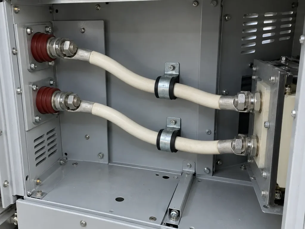
The Use field reads “Internal wiring of appliances.” Style 3321 at 4/0 AWG is intended for protected internal connections within an appliance, where the appliance design specifies Style 3321 and the rating and construction are appropriate.
The large conductor size does not widen this Use. Style 3321 is not building wire, facility feeder or branch-circuit wire, field wiring, tray or conduit wire, or external power cable. The Use record does not establish outdoor or wet-location suitability, and no such conclusion is drawn here. Whether the component is acceptable in a particular appliance is determined by that appliance’s own evaluation.
What UL Style 3321 Does and Does Not Define
The Style record defines the construction (single conductor, extruded insulation); the rating (150°C, 600 Vac, 750 Vdc, Horizontal flame); the conductor range and form (30 AWG–4/0 AWG, solid or stranded); the insulation material and the four-group thickness table; the covering (optional, treated or untreated braid); the marking field (General); and the Use (Internal wiring of appliances).
The Style record does not define:
- conductor material or plating
- strand count, strand diameter or lay length
- conductor area, conductor diameter or conductor resistance
- finished outside diameter or its tolerance
- current rating or ampacity
- braid material, treatment material or braid construction
- bend radius or flex performance
- terminal or connector hardware
- MOQ, stock, lead time or shipping terms
Common Procurement Errors
- Applying the 60/54 mil values of the 3–2 AWG group to 4/0 AWG.
- Treating 80 mils as the nominal wall and calculating a finished diameter from it.
- Assuming every Style 3321 construction includes a braid, or that none does.
- Assigning a specific braid material or protective function on the basis of the Style wording.
- Omitting the braid requirement from the RFQ, leaving the finished construction undefined.
- Combining the ratings into a single “600V AC/DC” or other merged figure.
- Deriving a current rating from 4/0 AWG.
- Publishing generic 4/0 AWG conductor area or diameter figures as product specifications.
- Assuming VW-1, FT1 or another vertical flame rating.
- Specifying Style 3321 for wiring outside the appliance.
How to Specify UL 3321 4/0 AWG Optional-Braid Wire in an RFQ
The Style fixes the construction, 150°C, 600 Vac, 750 Vdc, Horizontal flame, extruded XLPE, the 80/72 mil requirement for 4/0 AWG, the optional-braid provision and the Use. Everything else is order-specific and should be stated by the buyer, not filled with assumed values:
- UL AWM Style 3321 requirement
- 4/0 AWG
- solid or stranded
- conductor material
- conductor plating or finish
- detailed stranding, if controlled
- whether the optional braid is required
- treated or untreated braid, if specified
- customer drawing
- required finished OD or OD tolerance
- terminal or connector interface
- colour
- quantity
- packaging
- marking
- documentation
- the appliance and the protected internal wiring location
UL Marking and Documentation
Style 3321 wire is supplied as UL-recognized component wire where supplied under qualified manufacturing scope. The marking field of the Style record reads “General” and does not prescribe a fixed print legend. UL marking is applied according to the confirmed ordered construction, including whether a braid is present, and marking should be confirmed at the order stage.
Applicable RoHS / REACH documentation can be confirmed according to the ordered construction. CE, UKCA, CSA, FT1, VW-1, CPR, VDE, DIN, EN and IEC are not declared for this product.
Commercial, origin, compliance and transport documents are identified during quotation and confirmed according to the order.