UL AWM Style 3271 — Optional Semi-Conductive Layer for Motor Lead and Appliance Internal Wiring
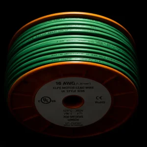
UL AWM Style 3271 is a 125°C maximum, 600 Vac / 750 Vdc extruded XLPE wire for use as motor leads or internal wiring of appliances, covering 30 AWG through 2000 kcmil. This page covers the optional semi-conductive polymeric layer construction available under UL AWM Style 3271 — a feature unique to this Style within the AWM XLPE family. The semi-conductive layer is an optional construction specified at the order stage; it is not a default feature of every UL AWM Style 3271 wire. CableApex supplies UL AWM Style 3271 with and without the optional semi-conductive layer from factory production in Yangzhou. CIF Hamburg and CIF Rotterdam export is available. UL AWM Style 3271 documentation is available for confirmed constructions on request.
The Semi-Conductive Layer — What It Does and Why It Is Specified
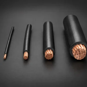
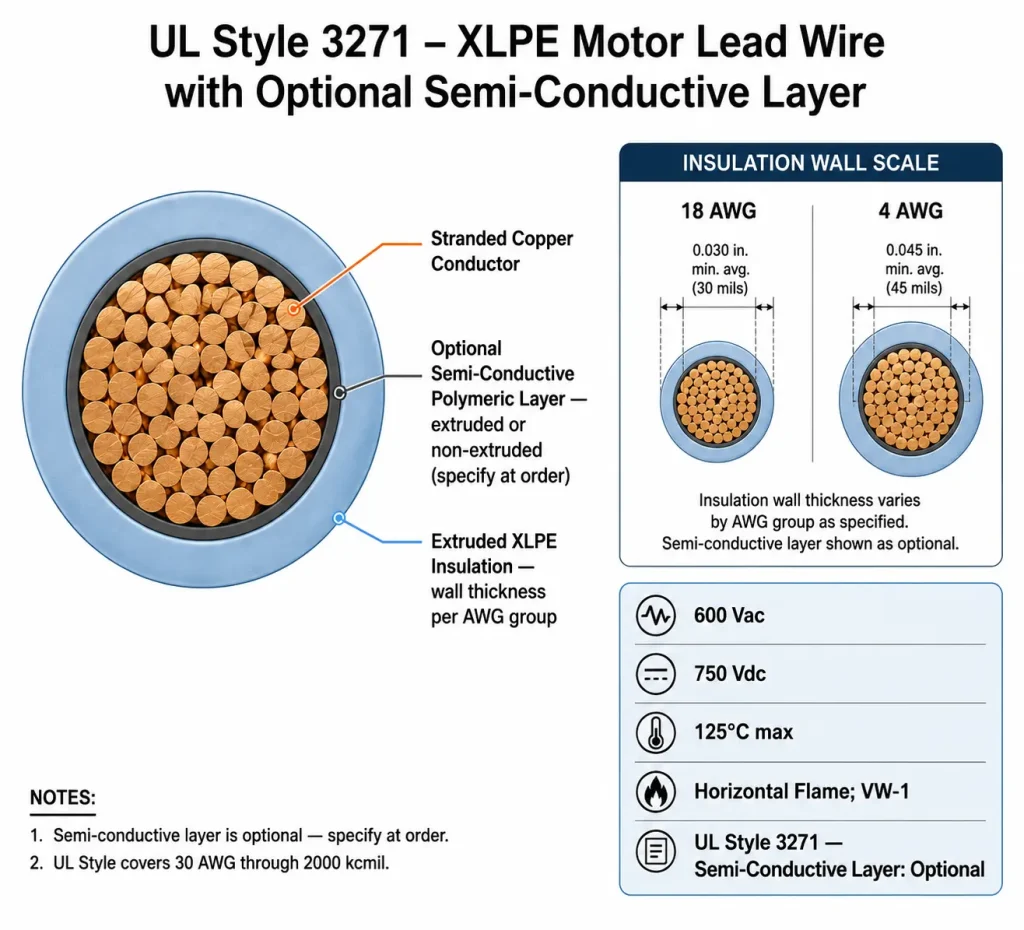
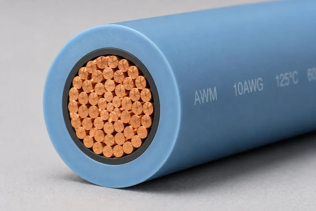
The optional semi-conductive polymeric layer is applied directly over the conductor strands, between the bare copper and the XLPE insulation. The material has a controlled intermediate electrical resistivity — neither a conductor nor an insulator — and its purpose is to create a smoother electrical interface at the conductor-insulation boundary.
A stranded copper conductor is not geometrically smooth: the individual wire strands create peaks and valleys at the conductor surface. When the conductor is energised at elevated voltage, the electric field is not uniform around the conductor — field concentration tends to occur at strand peaks, and air or void spaces in the gaps between strands can experience higher localised voltage stress than the surrounding XLPE insulation. In applications with smooth 50/60 Hz sinusoidal voltage at standard industrial levels, this non-uniformity is not typically a concern. In applications with non-sinusoidal waveforms, fast voltage transitions, or sustained high-frequency switching stress, the localised field concentration at conductor strand gaps can become a relevant insulation design factor.
The semi-conductive layer addresses this by filling the gaps between strands and presenting a continuous, smoother surface to the XLPE insulation. The result is a more uniform electric-field distribution at the conductor-insulation interface. Whether this construction is appropriate for a specific application depends on the motor system design, drive waveform characteristics, cable length, voltage level, and the insulation-system evaluation performed by the motor manufacturer or the relevant certification body. The semi-conductive layer is a construction option — its specification should be based on the requirements of the specific application and equipment design, not selected as a default for all motor lead applications.
UL AWM Style 3271 — Key Specifications
| Parameter | Value per UL Style 3271 File |
|---|---|
| UL AWM Style | 3271 |
| UL Subject / Section | 758, Section 3 |
| Temperature Rating | 125°C maximum |
| Voltage Rating | 600 Vac / 750 Vdc |
| AWG Range | 30 AWG – 2000 kcmil, solid or stranded |
| Insulation Material | Extruded XLPE (cross-linked polyethylene) |
| Semi-Conductive Layer | Optional — extruded or non-extruded semi-conductive polymeric layer over conductor; must be specified at order stage |
| Flame Rating | Horizontal flame; VW-1 vertical flame test available |
| UL Recognition | UL Recognized Component — file on record |
| Permitted Use (per UL Style file) | Motor leads or internal wiring of appliances; tags may indicate 2,500V peak — for electronic use only |
| Marking | Confirmed according to qualified construction, order requirement, and applicable UL marking rules |
| RoHS / REACH | Documentation available on request, where applicable |
Insulation Wall Thickness by Conductor Size Group
| Conductor Size Group | Min Average Thickness | Min at Any Point |
|---|---|---|
| 30–9 AWG | 30 mils (0.76 mm) | 27 mils (0.69 mm) |
| 8–2 AWG | 45 mils (1.14 mm) | 40 mils (1.02 mm) |
| 1–4/0 AWG | 55 mils (1.40 mm) | 50 mils (1.27 mm) |
| 213–500 kcmil | 65 mils (1.65 mm) | 58 mils (1.47 mm) |
| 501–1000 kcmil | 80 mils (2.03 mm) | 72 mils (1.83 mm) |
| 1001–2000 kcmil | 95 mils (2.41 mm) | 86 mils (2.18 mm) |
Inverter-Fed Motor Lead Applications — Engineering Context
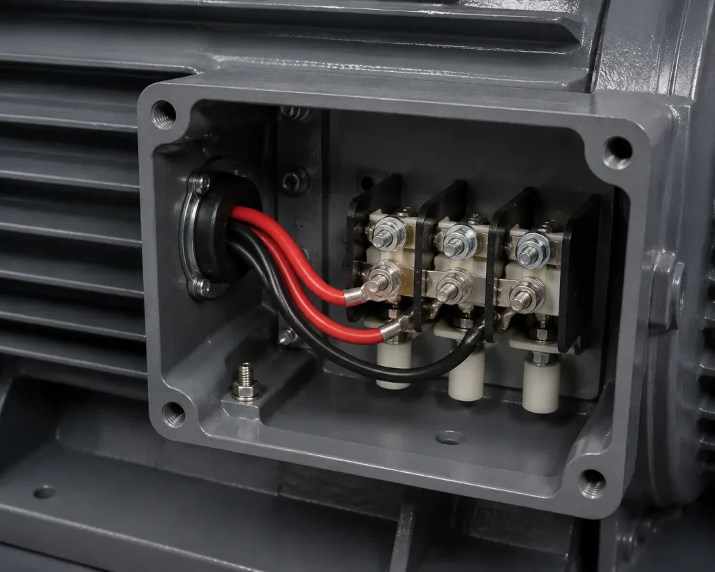
Motor engineers may evaluate UL AWM Style 3271 with optional semi-conductive layer for inverter-fed motor lead applications where conductor stress-control construction is part of the insulation-system design. The following is provided as engineering context for this evaluation — not as a certification claim.
Variable-frequency drives (VFDs) synthesize variable-frequency motor voltage using high-speed PWM switching, typically at 2–16 kHz. The resulting voltage at the motor terminal is not a smooth sine wave but a series of fast-transition pulses. Three characteristics of VFD-fed motor voltage are relevant to motor lead insulation design:
- Voltage overshoot at motor terminals. Impedance mismatch between the cable and motor can cause reflections that push peak voltage at the motor terminal above the DC bus voltage. The magnitude of this overshoot depends on cable length, drive output impedance, and motor input impedance — and should be evaluated for each specific drive-cable-motor combination.
- High dV/dt voltage transitions. Fast PWM switching creates high rates of voltage change across the insulation. The stress this places on the insulation-conductor interface is greater than that experienced with direct-line 50/60 Hz sinusoidal voltage.
- Repetitive switching stress. PWM transitions occur thousands of times per second. Any insulation degradation mechanism that would progress slowly under single-event stress may accumulate more rapidly under repetitive high-frequency switching.
Motor engineers specifying motor lead wire for inverter-fed applications where conductor stress-control construction is part of the insulation-system design should evaluate whether the optional semi-conductive layer of UL AWM Style 3271 is appropriate for their specific application. Final suitability depends on the motor system design, drive waveform characteristics, cable length, operating voltage, termination method, and the applicable test requirements of the motor and drive system evaluation. UL AWM Style 3271 is an appliance wiring material — it is not an independently VFD-certified cable system.
Engineering Notes — Semi-Conductive Layer Specification and Handling
- Extruded vs non-extruded semi-conductive layer — which to specify: UL AWM Style 3271 permits both extruded and non-extruded semi-conductive layer constructions. Extruded semi-conductive layer is applied as a continuous polymer coating during extrusion, producing a consistent, uniform layer across the conductor length. Non-extruded layer is typically applied as a tape wrap over the conductor before insulation extrusion. For most production-volume motor lead applications, extruded semi-conductive layer is the standard specification. Non-extruded construction is occasionally used for very large kcmil conductor sizes where extruded application is impractical. Confirm the construction type at the enquiry stage.
- Termination and stripping requirements: At the termination point, the semi-conductive layer must be removed cleanly along with the XLPE insulation when stripping the wire. Leaving semi-conductive material on the conductor between the strip point and the termination connection can create a localised conductivity path at the termination that may affect the electrical interface at that point. Use stripping tools compatible with the semi-conductive layer construction, or perform a conductor surface cleanup after rough stripping. Confirm the strip and termination procedure with the terminal hardware supplier for the specific production assembly.
- Specify semi-conductive layer before the first production order: The semi-conductive layer affects the wire’s construction, outer diameter, and production setup. A production run configured for standard UL AWM Style 3271 without the semi-conductive layer cannot be converted mid-run. For OEM motor designers developing a new motor design that may require the semi-conductive layer construction, confirm this specification before placing the first production order to avoid construction changes after production has begun.
Factory Supply for Germany — CIF Hamburg and Rotterdam
- Direct factory production: UL AWM Style 3271 with optional semi-conductive layer is produced at the Yangzhou facility and supplied through CableApex for B2B export. CIF Hamburg and CIF Rotterdam shipping available — transit approximately 25–30 days from Shanghai or Ningbo origin port.
- AWG range and semi-conductive options: Standard UL AWM Style 3271 (without semi-conductive layer) and the optional semi-conductive variant are both available. Semi-conductive construction may require a higher minimum order quantity than standard XLPE due to the additional production process step — confirm MOQ at the enquiry stage based on AWG, construction type, and quantity.
- Documentation: UL AWM Style 3271 documentation available for confirmed constructions on request. RoHS and REACH documentation available on request where applicable. Commercial Invoice, Packing List, Certificate of Origin (CCPIT), Bill of Lading provided as standard. HS Code: 8544.49. B2B quotation response within 12 hours.
Related UL AWM Styles
Buyers evaluating UL AWM Style 3271 with semi-conductive layer may also consider: UL AWM 3266 (125°C / 300 Vac, extruded XLPE, 32–10 AWG, no semi-conductive option — lower-voltage XLPE alternative for 300V class motor lead and internal wiring); UL AWM 3321 (150°C / 600 Vac or 750 Vdc, extruded XLPE, 30 AWG–4/0 AWG — higher-temperature XLPE alternative for appliance internal wiring where 125°C is insufficient); UL AWM 1015 (80–105°C / 600 Vac or 750 Vdc, extruded PVC, 30 AWG–2000 kcmil — lower-temperature PVC alternative where XLPE or semi-conductive construction is not required); and UL AWM 3071 (200°C / 600 Vac, extruded silicone rubber with fiberglass braid, 18–13 AWG — silicone rubber alternative where 200°C temperature class is required).