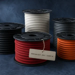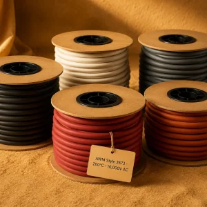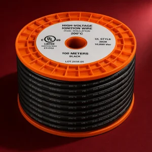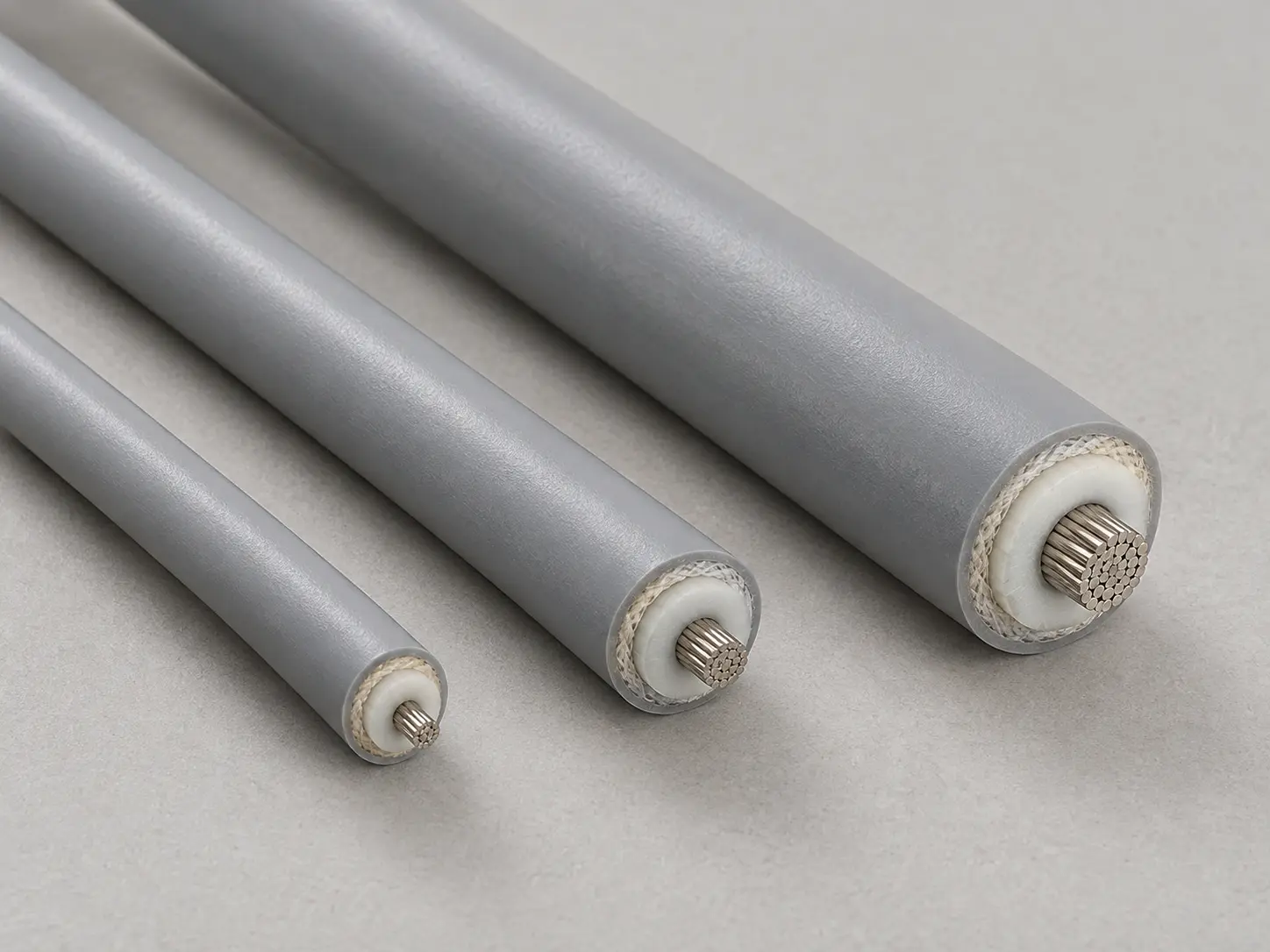
UL AWM Style 3573 — 10 Mil Outer Insulation Over Braid
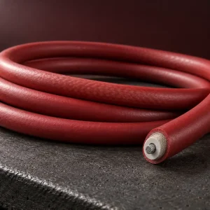
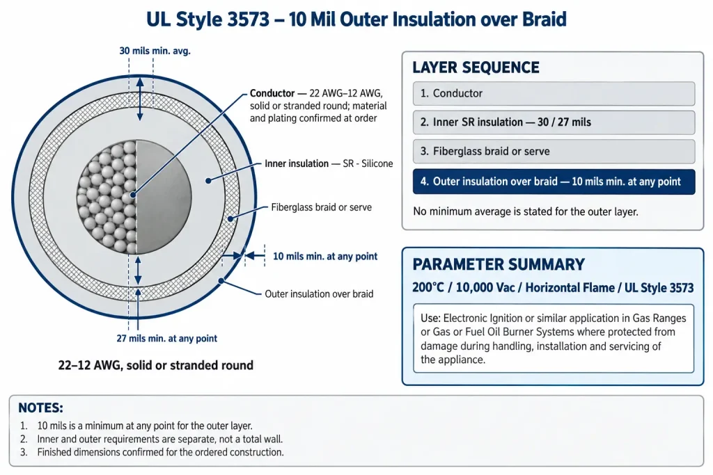
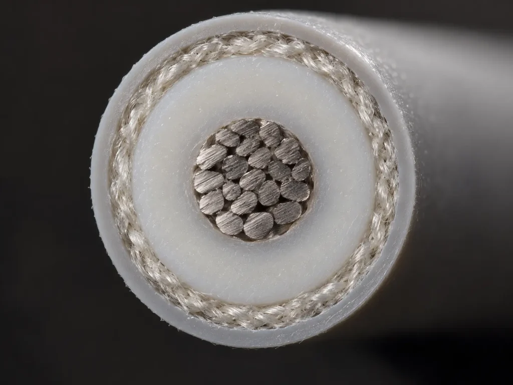
UL AWM Style 3573 is an insulated wire rated 200°C and 10,000 Vac with a Horizontal flame classification, covering 22 AWG to 12 AWG, solid or stranded round. Its construction has three parts: an inner SR silicone insulation, a fiberglass braid or serve, and an outer insulation applied over the braid. The Style record sets the outer insulation over the braid at 10 mils minimum at any point.
This page deals with that outer layer: what the 10-mil requirement means, how it differs from the inner insulation requirement, where the braid or serve sits between them, and what has to be confirmed for an ordered construction. For the broader Style overview and the other constructions offered under it, see the UL 3573 ignition lead wire category.
Verified UL 3573 Technical Specifications
| Parameter | UL AWM Style 3573 record |
|---|---|
| Style | 3573 |
| Description | Insulated Wire |
| Temperature | 200°C |
| Voltage | 10,000 Vac |
| Conductor range | 22 AWG – 12 AWG |
| Conductor form | Solid or stranded round |
| Inner insulation | SR – Silicone |
| Inner minimum average thickness | 30 mils (0.76 mm) |
| Inner minimum thickness at any point | 27 mils (0.69 mm) |
| Braid | Fiberglass braid or serve |
| Outer insulation | Over braid, SR – Silicone |
| Outer minimum thickness | 10 mils (0.25 mm) minimum at any point |
| Flame | Horizontal flame |
| Marking | General |
| Use | Electronic Ignition or similar application in Gas Ranges or Gas or Fuel Oil Burner Systems where protected from damage during handling, installation and servicing of the appliance. |
Four points in this table need clarification. First, the Insulation field of the record identifies the material as “SR – SILICONE” once and then states the inner and outer requirements under that entry. Second, the outer insulation has only a minimum-at-any-point value; the record states no minimum average for the outer layer. Third, the millimetre values are arithmetic conversions (1 mil = 0.0254 mm), not separate UL specifications. Fourth, the conductor entry defines size range and form only; conductor material, plating and strand construction are confirmed according to the ordered construction.
10 Mil Minimum Outer Insulation Over the Braid
The Style record states: “Outer insulation over braid – 10 mils min at any point.” Three things follow directly from that wording.
- Position: the outer insulation is applied over the braid. It is the layer outside the fiberglass braid or serve, not part of the inner insulation.
- Type of requirement: 10 mils is a minimum at any point. The thinnest point anywhere in the outer layer must not fall below 10 mils (0.25 mm by unit conversion).
- No average requirement: unlike the inner insulation, the outer layer has no stated minimum average. It is governed by the single at-any-point floor.
The 10-mil figure is therefore not a nominal, average or exact thickness, and it is not a total wall. The actual outer layer of an ordered construction may exceed 10 mils at many or all points; the Style sets only the floor. The outer requirement is also separate from the inner one. The record does not define a combined wall thickness, so the inner and outer values should not be added together as a single specification.
For the same reason, the finished outside diameter cannot be derived from conductor size plus the inner and outer thickness values, particularly as the braid or serve between them adds a layer the Style does not dimension. Where a drawing controls finished diameter, for example to suit a grommet, clip or routing channel, the requirement belongs in the RFQ and is confirmed against the ordered construction.
The record assigns no performance function to the outer insulation. It does not state that the outer layer provides moisture sealing, chemical or oil resistance, abrasion or cut resistance, weather or outdoor suitability, contamination resistance or longer service life, and none of these properties is attributed to it here. The outer insulation is a construction element with a defined minimum thickness, nothing more.
30 Mil Average / 27 Mil Minimum Inner SR Silicone
The inner insulation is SR silicone with two separate requirements:
- 30 mils (0.76 mm) minimum average: the average of wall-thickness measurements around the inner insulation must not fall below 30 mils.
- 27 mils (0.69 mm) minimum at any point: the thinnest point anywhere in the inner wall must not fall below 27 mils.
A qualified construction must meet both. A wall averaging above 30 mils still fails if one point is below 27 mils, and a wall with no point below 27 mils still fails if its average is below 30 mils. The two figures are floors, not a tolerance band, and 30 mils is not a nominal wall. The inner requirement applies across the full 22–12 AWG range.
Comparing the two insulation requirements shows the structure of the Style: the inner layer carries both an average and a point minimum, while the outer layer over the braid carries a point minimum only.
Fiberglass Braid or Serve Between the Insulation Layers
The braid field of the Style record reads “Fiberglass braid or serve.” The intermediate element is therefore fiberglass, applied either as a braid or as a serve. Both forms are permitted by the Style wording, and the element sits between the inner insulation and the outer insulation.
The record does not specify braid density, braid angle, yarn size, fiberglass grade, treatment, coating or weave construction, and it attributes no mechanical or other performance to the braid or serve. If a drawing requires the braid form specifically, or a serve, or any detail of the fiberglass construction, that requirement should be written into the RFQ and confirmed for the ordered qualified construction.
200°C / 10,000 Vac / Horizontal Flame
The rating field reads “200 deg C, 10000 Vac, Horizontal flame.” 200°C is the rated temperature of the Style. The record gives no continuous-duty or long-term qualifier, and no thermal margin or expected life is derived from it here.
10,000 Vac, or 10 kV AC, is the voltage rating. The record states no DC rating and no higher voltage value, and it gives no dielectric-withstand figure beyond the rating itself. The Style also says nothing about ignition pulse waveform, frequency, duty cycle or spark energy, and no such characteristics are inferred.
Horizontal flame is the flame classification in the record. It is not VW-1, FT1 or FT2, and no vertical flame rating forms part of the Style.
22–12 AWG Solid or Stranded Round
The conductor field reads “22 AWG – 12 AWG solid or stranded round.” This covers 22 AWG through 12 AWG in solid or stranded round form. The inner and outer insulation requirements and the braid-or-serve element apply across the whole range.
The conductor field does not define conductor material, plating, strand count, strand diameter, lay length or conductor resistance, and the Style assigns no current rating. Where a drawing controls any of these, they are confirmed for the ordered construction.
Official Ignition Use and Protection Requirement
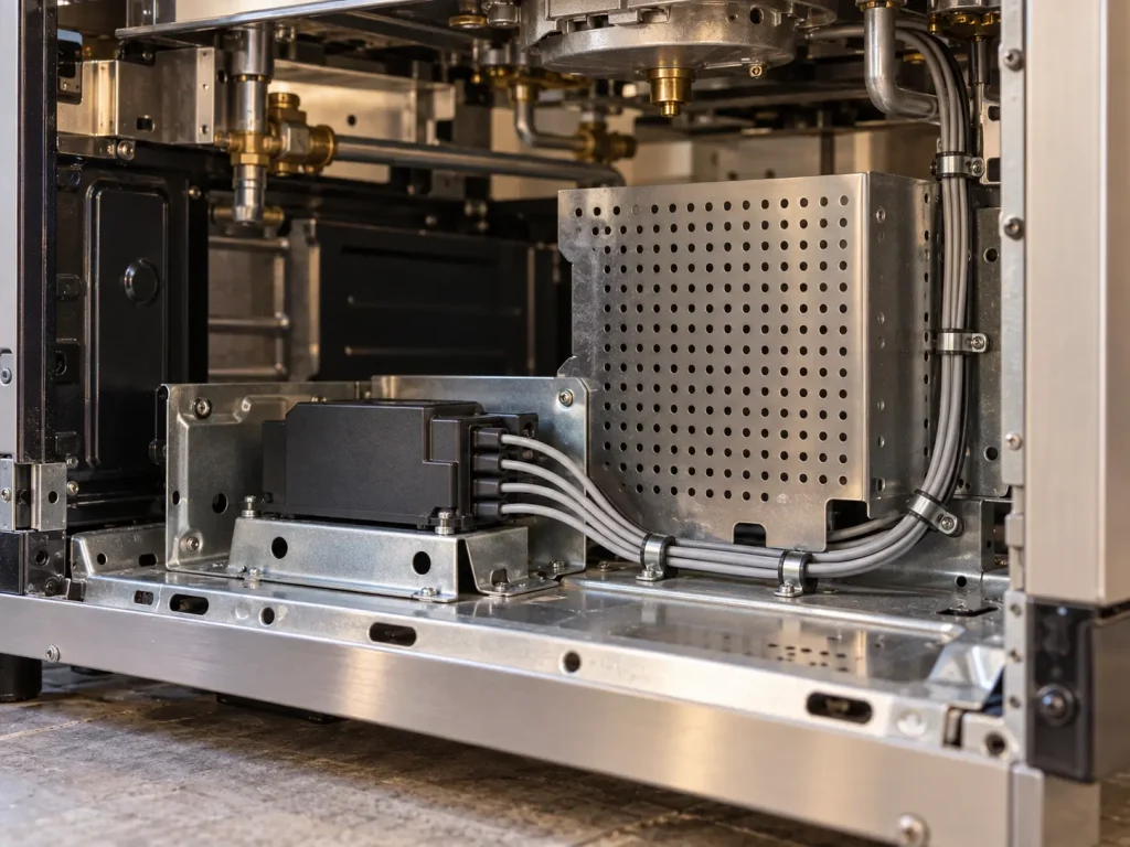
The full Use wording of Style 3573 is: “Electronic Ignition or similar application in Gas Ranges or Gas or Fuel Oil Burner Systems where protected from damage during handling, installation and servicing of the appliance.”
The Use has two parts that belong together. The first defines the application: electronic ignition or similar applications in gas ranges, gas burner systems or fuel oil burner systems. The second is a condition: the wire must be protected from damage during handling, installation and servicing of the appliance. The condition is part of the Use, not an optional note, and simply locating the wire inside an enclosure does not by itself show it is met.
The Use does not extend to exposed outdoor routing, direct weather or flame exposure, open routing, building or field wiring, facility high-voltage wiring, general 10 kV power distribution, transformer secondary distribution, spark-plug cable or automotive ignition cable. The outer insulation over the braid does not widen this boundary.
What Style 3573 Does and Does Not Define
The Style record defines the rating (200°C, 10,000 Vac, Horizontal flame); the conductor range and form (22–12 AWG, solid or stranded round); the insulation material (SR – Silicone) with its inner requirement (30 mils minimum average, 27 mils minimum at any point) and outer requirement (10 mils minimum at any point, over braid); the braid element (fiberglass braid or serve); the marking field (General); and the Use with its protection condition.
The Style record does not define:
- a minimum average thickness for the outer insulation
- a total or combined wall thickness
- conductor material, plating or strand construction
- conductor resistance or current rating
- finished outside diameter or its tolerance
- braid density, angle, yarn or treatment
- a DC rating or dielectric-withstand values
- environmental, chemical or mechanical performance
- colours, put-up lengths or packaging
Common Procurement Errors
- Treating 10 mils as the nominal or average outer thickness.
- Adding inner and outer values into a single “total wall” figure.
- Calculating finished diameter from the insulation values.
- Writing “fiberglass braid” alone when the Style permits braid or serve.
- Attributing sealing, moisture, chemical or outdoor performance to the outer insulation.
- Shortening the Use and dropping the protection condition.
- Assuming a conductor material or plating is part of the Style.
- Adding a DC rating or a voltage above 10,000 Vac.
- Assuming VW-1, FT1 or another vertical flame rating.
How to Specify UL 3573 10 Mil Outer-Insulation Wire in an RFQ
The Style fixes the rating, conductor range and form, the inner and outer insulation requirements, the braid-or-serve element and the Use. The following should be stated by the buyer and confirmed for the ordered construction, not filled with assumed values:
- AWG within 22–12 AWG
- solid or stranded round
- requested conductor material
- requested conductor finish or plating
- detailed stranding, if controlled
- braid or serve, if the drawing specifies one
- any outer-insulation thickness requirement above the 10-mil Style minimum, if the drawing controls it
- colour
- required finished OD or dimensional limit
- marking requirement
- quantity
- packaging
- required documents
- equipment type
- ignition application
- routing location
- protection conditions during handling, installation and servicing
UL Marking and Documentation
Style 3573 wire is supplied as UL-recognized component wire where supplied under qualified manufacturing scope. The marking field of the Style record reads “General” and does not prescribe a fixed print legend. UL marking is applied according to the confirmed ordered construction and should be confirmed at the order stage. Component recognition does not by itself establish the approval of the end equipment.
Applicable RoHS / REACH documentation can be confirmed according to the ordered construction. CE, UKCA, CSA, FT1, VW-1, CPR, VDE, DIN, EN and IEC are not declared for this product.
Commercial, origin, compliance and transport documents are identified during quotation and confirmed according to the order.