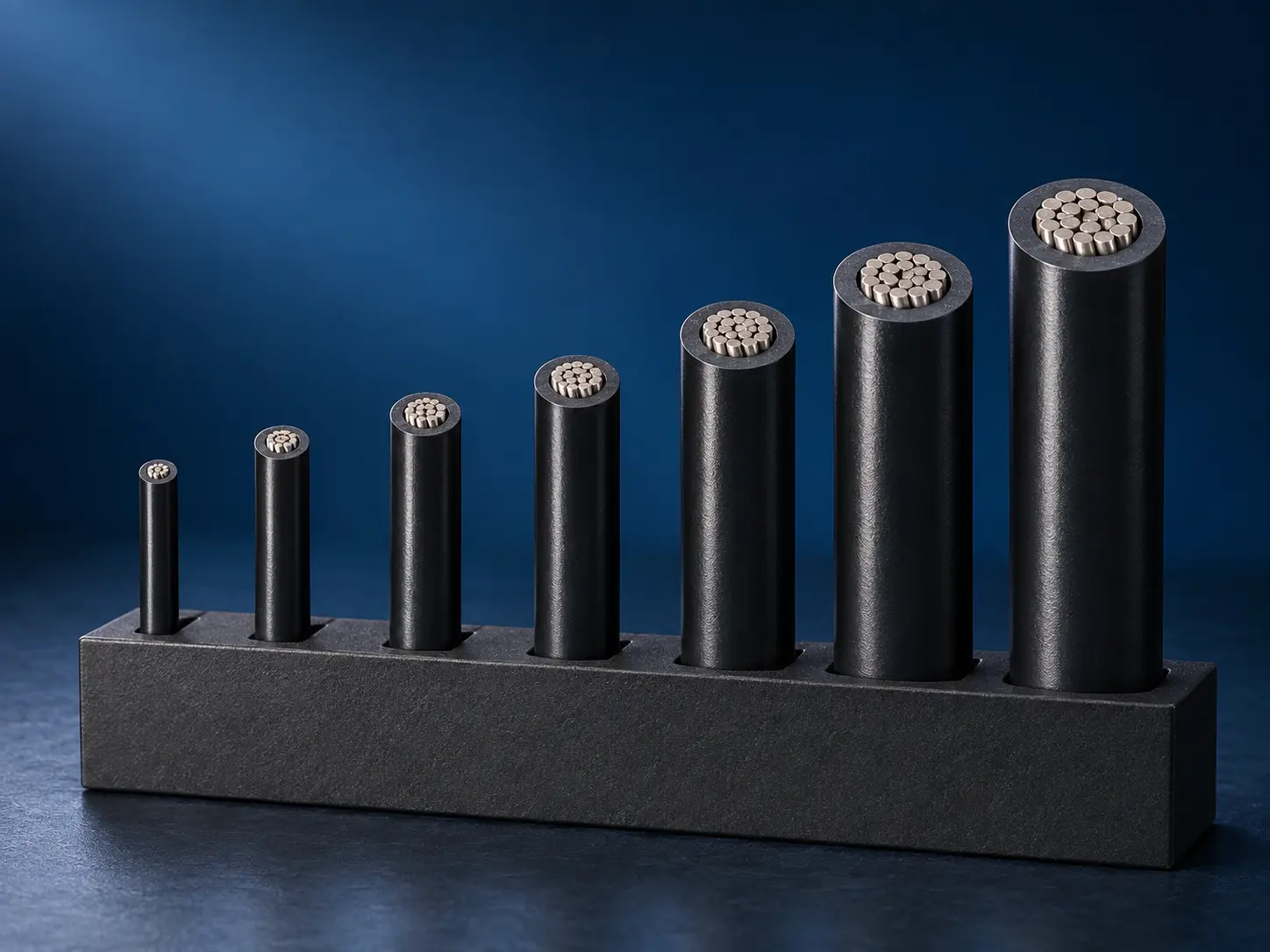
UL 1569 30–2 AWG 300V PVC Wire
UL AWM Style 1569 is a single conductor with extruded PVC insulation, rated 300 Vac with a Horizontal Flame designation and available in 80°C, 90°C and 105°C ratings. What distinguishes it in a specification is the breadth of its conductor scope: 30 AWG through 2 AWG, in solid or stranded construction.
That range spans fine internal leads at one end and substantially heavier conductors at the other, and the Style does not apply one insulation requirement across all of it. The wall is defined in two conductor-size groups, and identifying which group governs an ordered size is the first step in writing an accurate Style 1569 specification.
The official Use applies throughout the range: internal wiring of appliances or electronic equipment where not subjected to movement or mechanical damage.
Confirmed UL Style 1569 Specifications
| Parameter | Requirement |
|---|---|
| UL AWM Style | 1569 |
| Description | Single Conductor with extruded insulation |
| Temperature Ratings | 80°C / 90°C / 105°C |
| Voltage | 300 Vac |
| Flame | Horizontal Flame |
| Conductor Range | 30 AWG–2 AWG |
| Conductor Construction | Solid or stranded |
| Insulation | Extruded PVC |
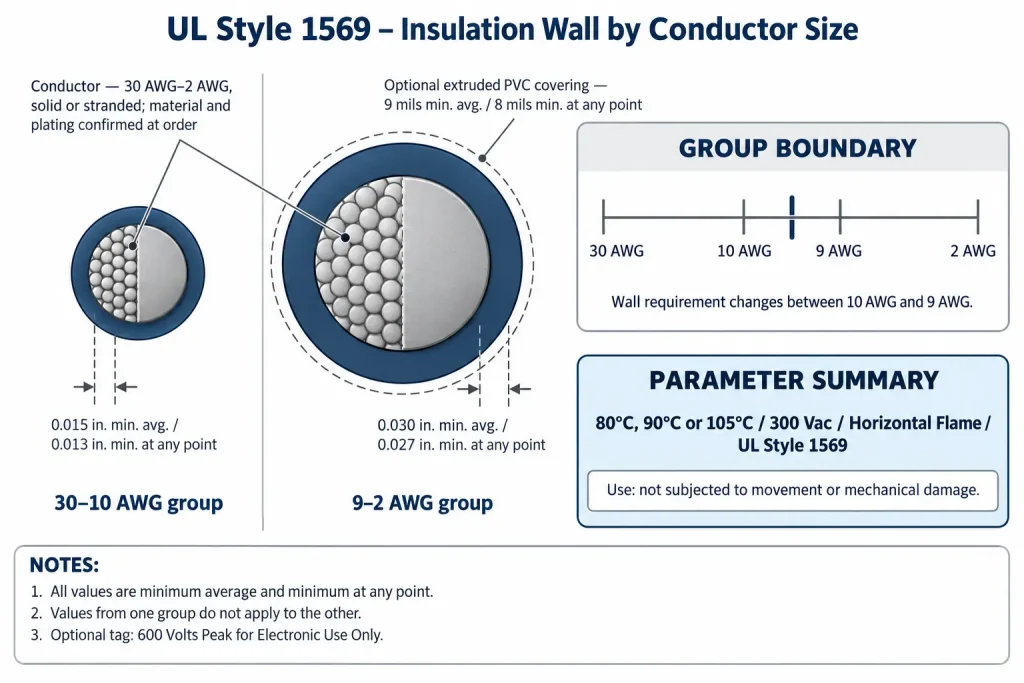
| 30–10 AWG Insulation | 15 mil minimum average / 13 mil minimum at any point |
| 9–2 AWG Insulation | 30 mil minimum average / 27 mil minimum at any point |
| Optional PVC Covering | 9 mil minimum average / 8 mil minimum at any point |
| Marking | General |
| Use | Internal wiring of appliances or electronic equipment where not subjected to movement or mechanical damage |
| Optional Tag | 600 Volts Peak for Electronic Use Only |
| RoHS / REACH | Applicable RoHS / REACH documentation can be confirmed according to the ordered construction |
Nine points to clarify about the table above:
- The insulation wall requirement depends on the conductor-size group, and values from one group do not apply to the other.
- Within each group, the minimum average and the minimum at any point are two independent requirements, not a range and not a nominal wall.
- The three temperature ratings exist within the Style; the applicable rating must match the confirmed ordered construction.
- The PVC covering is optional and is supplied only where the ordered construction supports it and the buyer specifies it.
- The covering’s 9/8 mil values apply to that layer alone and are not added to the insulation wall to produce one figure.
- The normal voltage rating is 300 Vac. The record gives no DC rating.
- 600 Volts Peak for Electronic Use Only is a tag statement, not the normal working-voltage rating.
- Conductor material, plating, strand count, strand diameter and lay length are not defined by the Style.
- Finished OD, OD tolerance, conductor resistance, metric cross-section and ampacity are not defined by the Style, and the Style range is not a stock list.
30 AWG to 2 AWG Conductor Range
The confirmed conductor scope runs from 30 AWG to 2 AWG, and every size between those limits falls within the Style. Sizes finer than 30 AWG and heavier than 2 AWG are outside it, so a specification or legacy listing extending beyond either limit contains a requirement the Style record does not support.
Both conductor forms are permitted across the whole range. Solid and stranded are alternatives within Style 1569 rather than properties tied to particular sizes, so a drawing that controls the form should state which is required at each size.
The Style assigns no circuit function or current capacity to any size. It does not designate fine sizes as signal or control wire, or heavier sizes as power conductors, and it gives no ampacity. No current value is inferred here from conductor size, the temperature rating, the voltage rating or the insulation wall. Where a circuit requirement exists, it is evaluated through the buyer’s equipment design and the applicable approval process.
Style scope is also not availability. The range describes what can be qualified under Style 1569, not what is produced or held, and a given size, form, colour and construction is confirmed per enquiry.
Insulation Wall for 30–10 AWG
For conductor sizes 30 AWG through 10 AWG, the extruded PVC wall must satisfy two conditions together: an average thickness of at least 15 mils, and a thickness of at least 13 mils at every point around the conductor.
These measure different things. The first is an averaged figure for the wall as a whole, so a construction satisfies it across the section. The second is a local floor: no single point of the wall may fall below it, whatever the average reads. A wall that averaged 15 mils but thinned below 13 mils somewhere on the circumference would not meet the requirement, and a wall held at 13 mils throughout would not meet the average.
Both are minimums rather than targets. The record states no nominal wall, no tolerance band and no manufacturing allowance, so an actual construction may sit above these figures, and how far above belongs to that construction rather than to the Style.
Insulation Wall for 9–2 AWG
For conductor sizes 9 AWG through 2 AWG, the requirement is a separate confirmed group: 30 mils minimum average and 27 mils minimum at any point. The two values are structured exactly as in the first group and apply together in the same way.
The step between the groups is substantial, and errors occur in both directions. Describing the whole Style as a 15 mil construction understates the requirement for every size from 9 AWG upward. Applying the 30 mil figure to a 20 AWG requirement overstates it. Where a specification covers sizes on both sides of the boundary, it carries both sets of values rather than one, and the boundary itself sits between 10 AWG and 9 AWG.
The heavier group is a wall requirement for larger conductors, nothing more. The record attaches no performance characterisation to it, so this page does not describe it as a heavy-duty or reinforced construction, does not infer higher current capacity from the thicker wall, and draws no relationship between wall thickness and mechanical durability in either direction.
Neither group produces a finished outer diameter, and this page publishes no AWG-to-diameter, conductor resistance or current table. Actual OD depends on the conductor material and form, the actual conductor dimensions, the applicable insulation group, whether the optional covering is applied, the PVC extrusion and manufacturing tolerance. Where grommet fit, terminal entry or routing clearance is controlled by the design, state a maximum finished OD and an OD tolerance in the RFQ so the proposed construction can be checked against the actual requirement.
80°C, 90°C and 105°C Ratings
UL Style 1569 includes 80°C, 90°C and 105°C ratings. The applicable rating must match the confirmed ordered construction, so an enquiry naming only the Style leaves that open, and a listing presenting Style 1569 as a single-temperature product omits part of the record.
A given wire carries the rating confirmed for its qualified construction rather than a selection from a menu, and the three ratings are not automatically all available in every configuration. A buyer whose equipment specification controls a wire temperature rating should state the required rating explicitly, or supply the drawing that states it.
The ratings are stated without duty qualifiers. This page does not describe any of them as continuous, derives no service life, thermal cycling count or thermal margin from them, and publishes no threshold at which one rating should be selected over another. No rating above 105°C belongs to this Style.
Protected Internal Wiring Use
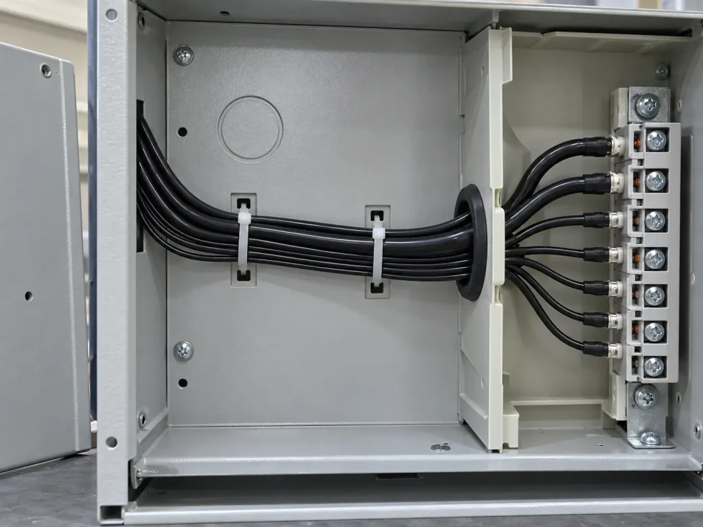
The official Use is “Internal wiring of appliances or electronic equipment where not subjected to movement or mechanical damage.” It applies to the whole Style, at every conductor size and in both conductor forms.
Three elements shape how the Style is specified. The Use covers appliances and electronic equipment, and dropping either term narrows it incorrectly. The movement restriction excludes positions where movement is an intended or expected part of service, including repeated flexing, continuous-flex or drag-chain routing, hinged or sliding component connections and robotic or servo motion. And the mechanical-damage restriction excludes exposed or unprotected routing, abrasive contact points and positions where the wire may be crushed, pinched or struck, with protection at the routing position coming from the equipment design.
The record states these limitations and quantifies nothing beyond them. It defines no flex-cycle count, bend radius, vibration, abrasion, crush or impact value, so none appears on this page, and a stranded conductor is a permitted construction rather than an indication that the wire is intended for movement.
The Use is also internal wiring and is not extended here to building wire, field wiring, branch circuits, conduit or tray wiring, external wiring, portable cord, motor power cable, facility power distribution or outdoor wiring. Compliance of a finished appliance or assembly is established at the equipment level and is not conferred by the Style designation of one internal wire.
Optional PVC Covering
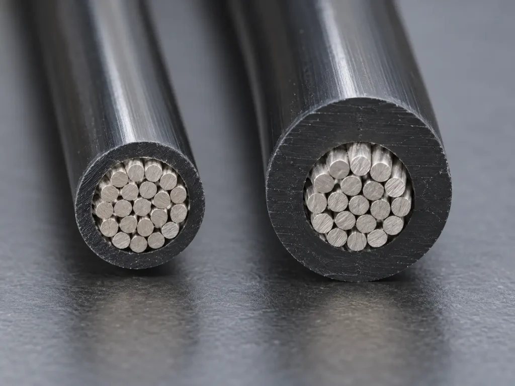
As a secondary option, the Style may include an extruded PVC covering with 9 mils minimum average thickness and 8 mils minimum thickness at any point, where the confirmed ordered construction supports it.
It is not included unless specified, its two values apply to that layer alone, and each is a minimum rather than a nominal thickness. The record assigns the covering no function, so no mechanical armor, higher voltage or temperature rating, chemical resistance, waterproofing, shielding, EMI protection or flexibility qualification is claimed for it, and it does not relax the use limitation described above.
300 Vac and the Optional 600 Volts Peak Tag
The normal Style rating is 300 Vac, and that is the figure that belongs in a specification.
Separately, the tag may state 600 Volts Peak for Electronic Use Only. Both qualifiers stay attached whenever that statement is cited: it is a peak indication for electronic use rather than a working voltage, it does not replace or raise the 300 Vac rating, and it does not widen the official Use. Writing the Style as 300–600 V, 600 Vac or 600 V continuous misstates the record, and the record gives no DC rating.
In an enquiry the two stay distinct: the voltage requirement is stated against the 300 Vac rating, and any need for the peak tag statement is listed separately as a marking and construction question.
How to Specify UL 1569 in an RFQ
A Style designation is a construction requirement, not a complete purchase specification. A complete enquiry states:
- the UL AWM Style 1569 requirement
- the required AWG within 30 AWG–2 AWG
- the required temperature rating
- solid or stranded construction
- conductor material or plating, if controlled by the drawing
- insulation colour
- whether the optional PVC covering is required
- marking requirements
- the drawing or BOM
- documentation requirements
- quantity and packaging
- destination and Incoterm
The Style data alone does not define strand count, finished OD, conductor resistance, ampacity, current rating, MOQ, lead time or stock availability. Those are confirmed separately against the ordered construction, and applicable product marking should be confirmed according to the ordered construction.
Order quantity, packaging, destination, Incoterm and commercial terms should be confirmed with the RFQ and are established case by case after review.
What Style 1569 Does and Does Not Define
Style 1569 defines:
- 80°C, 90°C and 105°C temperature ratings
- 300 Vac voltage rating
- Horizontal Flame
- conductor range 30 AWG–2 AWG, solid or stranded
- extruded PVC insulation: 15/13 mils for 30–10 AWG and 30/27 mils for 9–2 AWG
- an optional extruded PVC covering at 9 mil minimum average / 8 mil minimum at any point
- Marking: General
- Use: Internal wiring of appliances or electronic equipment where not subjected to movement or mechanical damage
- the optional tag statement 600 Volts Peak for Electronic Use Only
Style 1569 does not universally define:
- conductor material, plating, strand count, strand diameter or lay length
- a nominal insulation wall or a manufacturing tolerance
- finished OD, OD tolerance, conductor resistance, ampacity or metric cross-section
- flex cycles, bend radius, vibration, abrasion, crush or impact limits
- a function or performance for the optional covering
- a normal 600 V rating or any DC rating
- circuit function for any conductor size
- colour, reel length, MOQ, stock, lead time, production capacity or shipping term
Common Procurement Errors
- Quoting one insulation wall figure across the whole 30 AWG–2 AWG range.
- Applying the 15/13 mil values to 9–2 AWG, or the 30/27 mil values to finer sizes.
- Placing the group boundary anywhere other than between 10 AWG and 9 AWG.
- Omitting the minimum-at-any-point value, or treating the minimum average as a nominal wall.
- Deriving a finished OD from the minimum wall values.
- Inferring current capacity or mechanical durability from the heavier wall group.
- Describing Style 1569 as a single-temperature Style, or assuming all three ratings are available in every configuration.
- Describing Style 1569 as a 600 V wire, or dropping “for Electronic Use Only” from the tag statement.
- Assuming the conductor is tinned copper, or claiming a stranding class or flexibility grade.
- Reading a stranded conductor as permission for repeated movement.
- Extending the Use into field, external, portable, conduit or moving-machinery wiring.
- Treating the optional covering as included, or adding its thickness to the insulation wall.
RFQ Information to Confirm
Style and ratings
- UL AWM Style 1569 requirement
- Required AWG within 30 AWG–2 AWG
- Required temperature rating
- 300 Vac voltage rating requirement
- Whether the optional peak tag statement is required
Conductor and construction
- Solid or stranded construction
- Conductor material and plating requirement, if controlled by the drawing
- Strand construction, if controlled
- Maximum conductor resistance, if controlled
- Whether the optional PVC covering is required
- Maximum OD and OD tolerance, if controlled
Identification and application references
- Insulation colour
- Marking requirements
- Internal wiring position, with confirmation that it is not subjected to movement or mechanical damage
- Drawing, BOM or equipment specification
Commercial
- Quantity and packaging
- Destination and Incoterm
- Requested UL marking and compliance documents, including any RoHS / REACH documentation requirement
UL Marking and Documentation
Supplied wire is UL-recognized component wire where supplied under a qualified manufacturing scope, with UL marking according to the confirmed ordered construction. The Style record lists Marking as General, and applicable product marking should be confirmed according to the ordered construction.
Applicable RoHS / REACH documentation can be confirmed according to the ordered construction. CE, UKCA, CSA, FT1, VW-1, CPR, VDE, DIN, EN, IEC and dual UL/CSA designations are not claimed here unless separately supported for the ordered construction.
Commercial, origin, compliance and transport documents are identified during quotation and confirmed according to the order.
Related Internal Links
- UL 1569 PVC Wire — category page for broad Style 1569 enquiries
- PVC Wire
- AWM Wire
- UL 1569 with optional extruded PVC covering — separate page for that confirmed construction detail
- UL 1569 for static internal wiring — separate page focused on the official use limitation