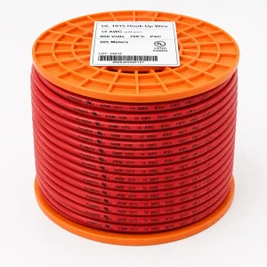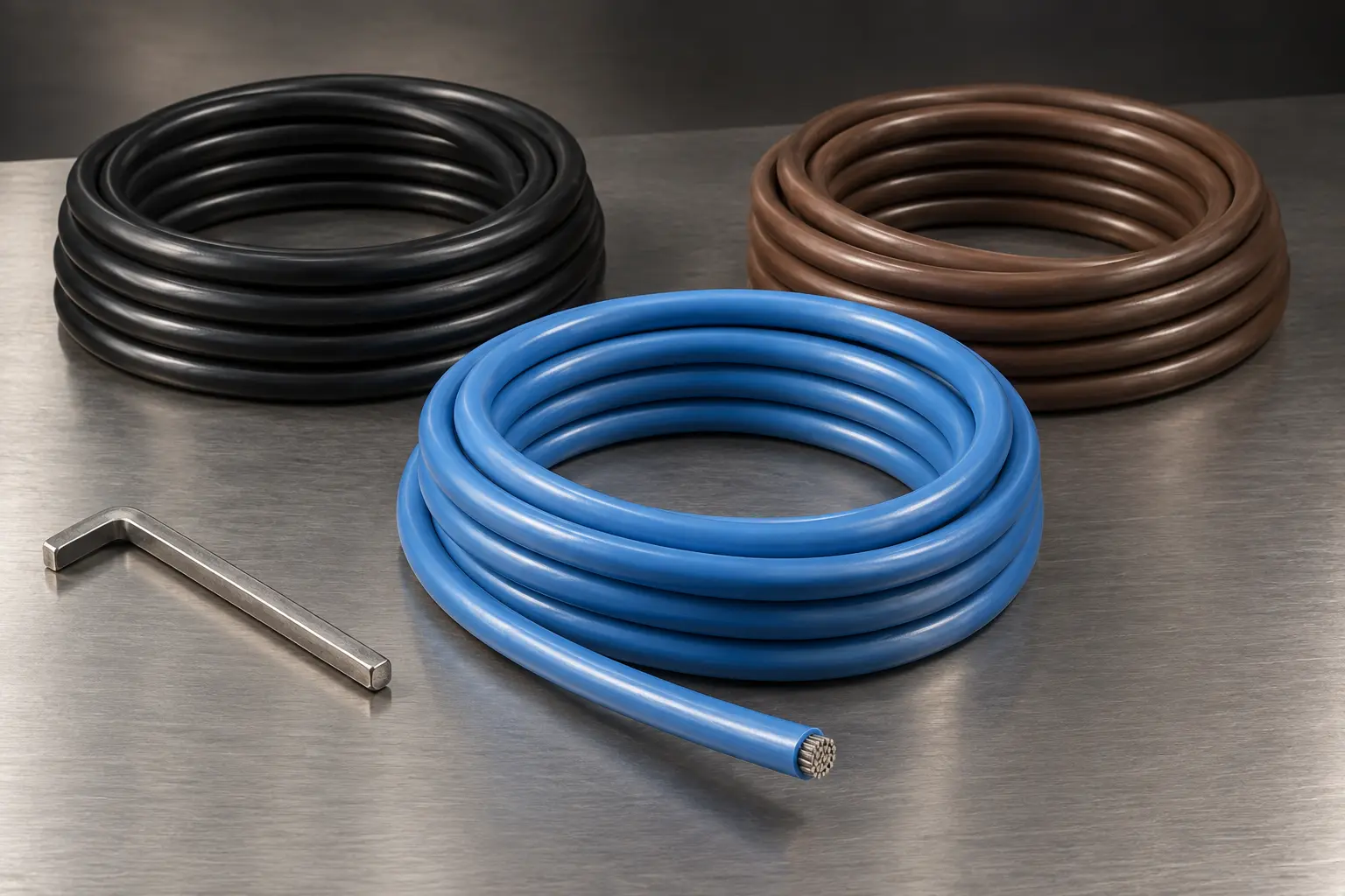
UL 1015 14 AWG 105°C 600V PVC Wire for Appliance Internal Wiring
This page covers UL AWM Style 1015 in 14 AWG, specified at the 105°C temperature option and the 600 Vac voltage option, for internal wiring of appliances. It is written for appliance and equipment OEM engineering and procurement teams whose drawing, BOM or wire specification calls for that construction in this conductor size.
Style 1015 is a single conductor with extruded PVC insulation. The record provides temperature rating options of 80°C, 90°C or 105°C and voltage rating options of 600 Vac or 750 Vdc, with a Horizontal Flame designation and an optional 60°C or 80°C Oil rating. The conductor range runs from 30 AWG to 2000 kcmil in solid or stranded form, and the official Use is “Internal wiring of appliances.”
14 AWG sits within the Style’s finest insulation group, which is a point worth stating early: the wall requirement that applies to 14 AWG is the same one that applies at 30 AWG, and it is not the heavier wall used for larger conductors.
Confirmed UL Style 1015 Construction and Ratings
| Parameter | Requirement |
|---|---|
| UL AWM Style | 1015 |
| Product Description | Single conductor with extruded insulation |
| Page-Specific Size | 14 AWG |
| Page-Specific Selection | 105°C temperature option, 600 Vac voltage option |
| Temperature Rating Options | 80°C, 90°C or 105°C |
| Voltage Rating Options | 600 Vac or 750 Vdc |
| Flame | Horizontal Flame |
| Optional Oil Rating | 60°C or 80°C Oil (optional) |
| Style Conductor Range | 30 AWG–2000 kcmil |
| Conductor Form | Solid or stranded |
| Insulation | Extruded PVC |
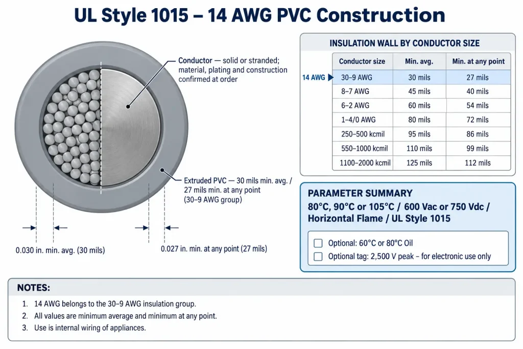
| Insulation Thickness for 14 AWG (30–9 AWG group) | 30 mil minimum average / 27 mil minimum at any point |
| Marking | General |
| Official Use | Internal wiring of appliances. |
| Optional Tag | 2,500 V peak – for electronic use only |
| Documentation | UL marking and compliance documents according to the confirmed ordered construction |
| RoHS / REACH | Applicable RoHS / REACH documentation can be confirmed according to the ordered construction |
| Conductor size | Minimum average thickness | Minimum thickness at any point |
|---|---|---|
| 30–9 AWG (includes 14 AWG) | 30 mils | 27 mils |
| 8–7 AWG | 45 mils | 40 mils |
| 6–2 AWG | 60 mils | 54 mils |
| 1–4/0 AWG | 80 mils | 72 mils |
| 250–500 kcmil | 95 mils | 86 mils |
| 550–1000 kcmil | 110 mils | 99 mils |
| 1100–2000 kcmil | 125 mils | 112 mils |
Nine points to clarify about the tables above:
- 80°C, 90°C and 105°C are alternative options. A 105°C construction is one selection within the Style, confirmed for the ordered construction.
- 600 Vac and 750 Vdc are likewise alternative options, not a combined AC/DC rating.
- 2,500 V peak – for electronic use only is an optional tag indication, not a normal working-voltage rating.
- The Oil rating is optional, and a 60°C or 80°C requirement must be stated by the buyer.
- 14 AWG belongs to the 30–9 AWG group, so the applicable requirement is 30 mil minimum average and 27 mil minimum at any point.
- Those two values are independent minimums, not a range and not nominal or exact wall values.
- The full group table is shown so the 14 AWG requirement is not confused with the heavier walls that apply to larger conductors.
- Conductor material, plating, strand count, strand diameter and lay length are not defined by the Style.
- Finished OD, OD tolerance, conductor resistance, metric cross-section and ampacity are not defined by the Style, and the Style range is not a stock list.
14 AWG and the 30–9 AWG Insulation Group
Style 1015 sets the extruded PVC wall in seven conductor-size groups. 14 AWG falls inside the first of them, so the requirement is 30 mils minimum average and 27 mils minimum at any point. Both conditions apply together: the average wall must meet the first figure, and no point of the wall may fall below the second. Neither is a nominal build.
This is where mid-gauge specifications most often go wrong. A 14 AWG conductor is substantial enough that buyers sometimes assume a heavier wall applies, but the 45, 60 or 80 mil figures belong to 8 AWG and larger and are not requirements for 14 AWG. Applying them would overstate the Style requirement just as quoting one universal figure across the range would understate it for large sizes.
Minimum wall values also do not produce a finished outer diameter. Actual OD depends on the conductor material and form, the actual strand construction and diameter, the PVC extrusion and manufacturing tolerance. Where grommet fit, terminal entry or routing clearance is controlled, state a maximum finished OD and OD tolerance in the RFQ rather than calculating one from the table. “Extruded PVC” is likewise not lead-free, halogen-free or LSZH material; PVC contains chlorine, and a halogen-free requirement is a different material specification.
Selecting the 105°C and 600 Vac Options
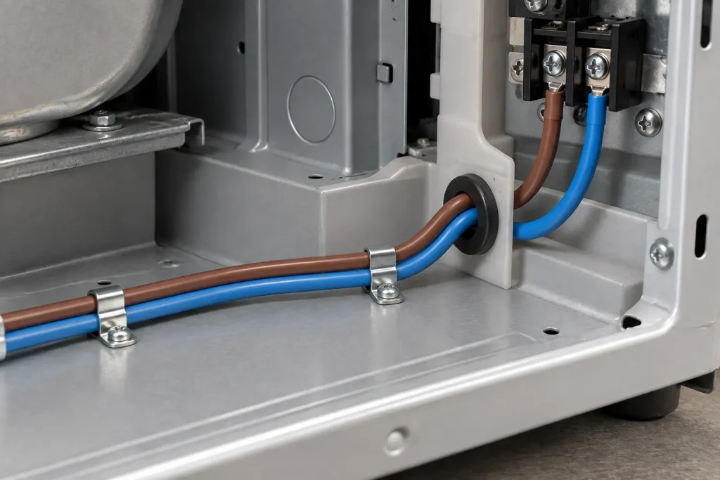
A Style 1015 construction carries the temperature and voltage ratings confirmed for it, so an enquiry naming only “UL 1015 14 AWG” leaves both open. Specifying 105°C selects the highest of the three temperature options rather than quoting a property the whole Style carries, and 600 Vac selects one of the two voltage options.
The ratings are stated without duty qualifiers, and no service life, thermal cycling count or thermal margin is derived from them here. The DC option is a DC rating for the wire and is never rewritten as an AC value or presented as an equipment system rating, so 600/750 V, 600 V AC/DC and 750 Vac all misstate the record.
Tags may additionally indicate “2,500 V peak – for electronic use only”. Both qualifiers stay attached whenever that tag is cited, and it does not widen the official Use. The flame designation is Horizontal Flame; VW-1, FT1 and vertical flame designations are not part of this record.
Conductor Construction at 14 AWG
The Style conductor information consists of the size range and the words solid or stranded, so at 14 AWG the following are RFQ fields rather than Style values:
- solid or stranded form
- conductor material
- plating or surface finish
- strand count, strand diameter and lay construction, where controlled
- maximum conductor resistance, where controlled
- metric cross-section, where a drawing specifies mm² rather than AWG
Descriptions such as “stranded tinned copper”, a stranding class or a flexibility grade belong to a specific product datasheet rather than to Style 1015, and none is claimed here. Conductor size also assigns no circuit function: the Style designates no size as a power, motor or supply conductor, gives no ampacity, and none is inferred here from 14 AWG, the 105°C option or the 600 Vac option. Current-carrying capacity is evaluated through the buyer’s equipment design and the applicable approval process.
Availability is a separate matter from Style scope. Not every size is produced or held in every option and colour, and a 14 AWG construction at the 105°C and 600 Vac selection is confirmed per enquiry.
Official Use: Internal Wiring of Appliances
The official Use is “Internal wiring of appliances.” This page keeps that wording and does not extend it to building or mains installation wiring, field wiring, conduit or tray installations, control cabinet field wiring, industrial power distribution or general power cable.
At this gauge, enquiries frequently arrive from contexts such as appliance internal leads, internal supply links, harness assemblies, power supply modules or OEM subassemblies. Those are buyer enquiry contexts that can be reviewed against the drawing, and they do not change the Use. Compliance of a finished appliance or assembly is established at the equipment level and is not conferred by the Style designation of one internal wire.
How to Specify UL 1015 14 AWG
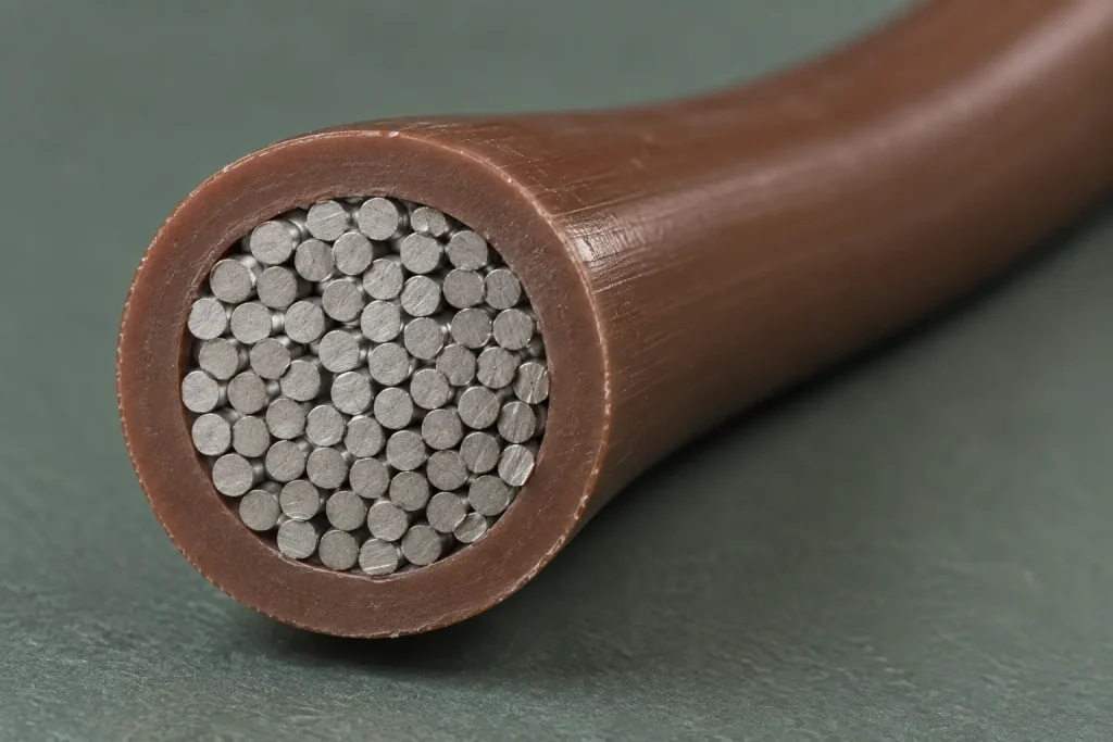
A Style designation is a construction requirement, not a complete purchase specification. A complete enquiry adds:
- the UL AWM Style 1015 requirement and the 14 AWG size
- the required temperature option, here 105°C
- the required voltage option, here 600 Vac
- solid or stranded construction
- conductor material and plating, where controlled by the drawing
- strand construction and maximum conductor resistance, where controlled
- whether an optional 60°C or 80°C Oil rating is required, and which
- insulation colour and any colour coding requirement
- the marking requirement
- maximum OD and OD tolerance, where controlled
- the appliance internal wiring location
- the drawing, BOM or wire specification
- documentation requirements, quantity and packaging or reel preference
- the destination and the requested Incoterm
What Style 1015 Does and Does Not Define
Style 1015 defines:
- 80°C, 90°C or 105°C temperature rating options
- 600 Vac or 750 Vdc voltage rating options
- Horizontal Flame
- optional 60°C or 80°C Oil
- conductor range 30 AWG–2000 kcmil, solid or stranded
- extruded PVC with size-dependent minimum wall requirements, 30 mil minimum average and 27 mil minimum at any point for the 30–9 AWG group that includes 14 AWG
- Marking: General
- Use: Internal wiring of appliances.
- optional tag: 2,500 V peak – for electronic use only
Style 1015 does not universally define:
- conductor material, plating, strand count, strand diameter or lay length
- a stranding class, flexibility grade or flex life
- finished OD, OD tolerance or bend radius
- conductor resistance, ampacity, current rating or metric cross-section
- equipment system voltage ratings
- halogen-free or LSZH material properties
- power-lead, motor-lead or supply-conductor suitability
- colour, reel length, MOQ, stock, lead time, production capacity or shipping term
Common Procurement Errors
- Treating 80, 90 and 105°C as one combined rating, or assuming 105°C without stating it.
- Writing “105°C continuous”.
- Writing “600V AC/DC”, or converting 750 Vdc into an AC value.
- Presenting 750 Vdc as an equipment system rating.
- Using 2,500 V peak as a working voltage, or dropping “for electronic use only”.
- Applying the 45, 60 or 80 mil wall values to 14 AWG.
- Quoting one insulation wall figure across the whole Style range.
- Omitting the 27 mil minimum-at-any-point requirement, or treating 30 mil as a nominal wall.
- Deriving a finished OD from the minimum wall values.
- Assuming the conductor is tinned copper, or claiming a stranding class or flexibility grade.
- Using a generic AWG-to-mm² conversion or resistance table as a product specification.
- Deriving ampacity from conductor size or the ratings.
- Describing PVC insulation as halogen-free or LSZH.
- Extending internal wiring of appliances into installation, panel field wiring or power distribution.
RFQ Information to Confirm
Style and ratings
- UL AWM Style 1015 requirement
- 14 AWG requirement
- Required temperature option: 80°C, 90°C or 105°C
- Required voltage option: 600 Vac or 750 Vdc
- Whether an optional 60°C or 80°C Oil rating is required, and which
Conductor and dimensions
- Solid or stranded construction
- Conductor material and plating requirement, if controlled by the drawing
- Strand construction, if controlled
- Maximum conductor resistance or controlled mm² cross-section, if applicable
- Maximum OD and OD tolerance, if controlled
Identification and application references
- Insulation colour and colour coding requirement
- Marking requirement
- Appliance internal wiring location
- The circuit requirement for engineering review, rather than a self-derived ampacity
- Drawing, BOM or wire specification
Commercial
- Quantity and packaging or reel preference
- Destination and requested Incoterm
- Requested UL marking and compliance documents, including any RoHS / REACH documentation requirement
UL Marking and Documentation
CableApex is an international sales and export company and does not hold a UL File for Style 1015. Supplied wire is UL-recognized component wire where supplied under a qualified manufacturing scope, with UL marking according to the confirmed ordered construction. The Style record lists Marking as General.
Applicable RoHS / REACH documentation can be confirmed according to the ordered construction. CSA, FT1, VW-1, CE, dual UL/CSA and halogen-free designations are not claimed here.
Commercial, origin, compliance and transport documents are identified during quotation and confirmed according to the order. They are not supplied as a fixed package with every shipment.