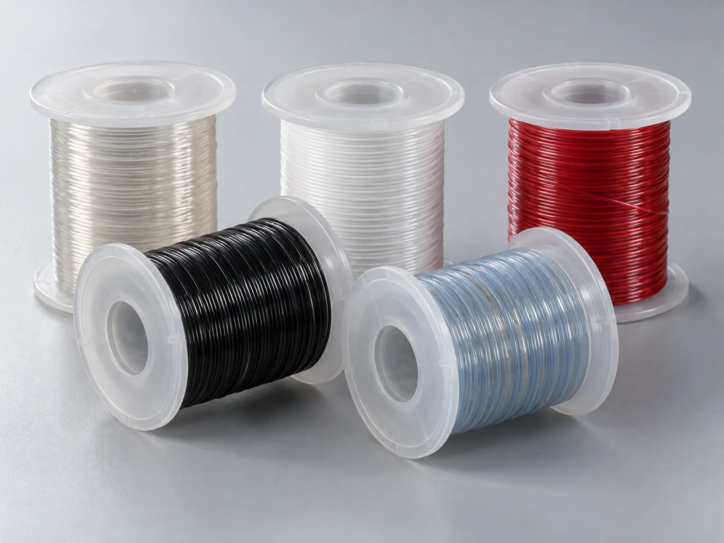
UL 10362 PFA Wire for Compact Electrical Assemblies
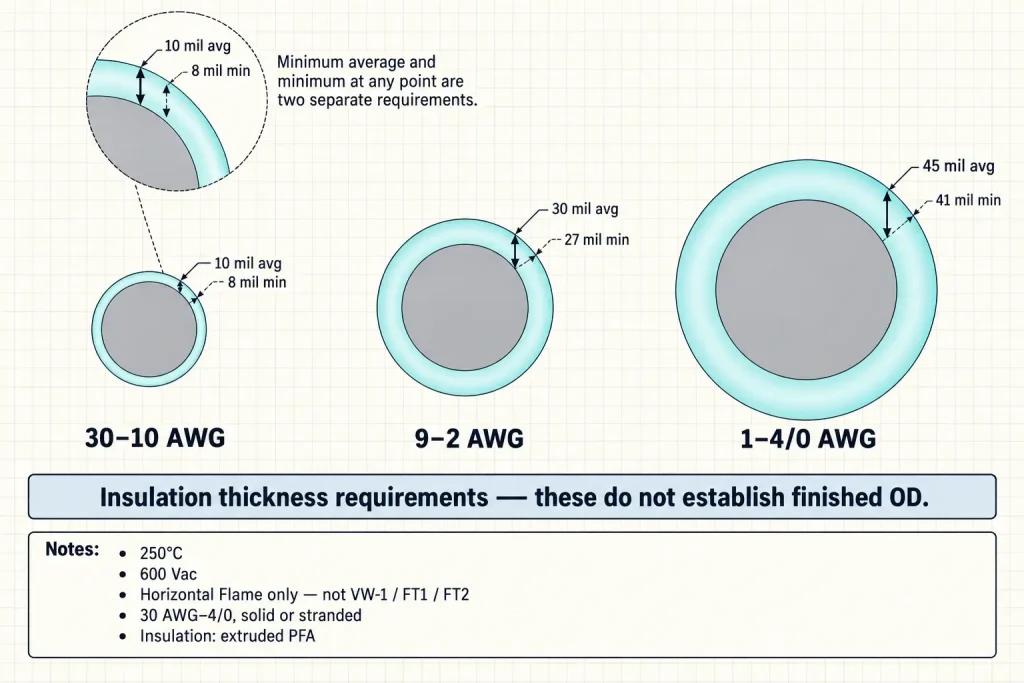
UL AWM Style 10362 is a single conductor with extruded insulation, rated 250°C and 600 Vac with Horizontal Flame. The insulation is extruded PFA. This page focuses on the 30–10 AWG conductor band, for which the Style specifies a 10 mil minimum average insulation thickness and 8 mils minimum at any point.
Those two figures are the reason this page is written for buyers working with restricted internal space. The 30–10 AWG band carries the lowest specified PFA insulation requirement in the Style, which makes it the band most often relevant when dimensional fit is a constraint. Final OD must still be confirmed for the ordered construction — the insulation figures alone do not establish it.
The official Use for Style 10362 is internal wiring. Compact electrical assemblies are a buyer application context within internal equipment wiring, not a UL classification, and nothing on this page should be read as UL designating any 10362 construction a “compact wire.”
UL 10362 Technical Specifications
| Parameter | Style-level information |
|---|---|
| UL AWM Style | 10362 (UL 758) |
| Description | Single Conductor with Extruded Insulation |
| Temperature rating | 250°C |
| Voltage rating | 600 Vac |
| Flame | Horizontal Flame |
| Complete Style range | 30 AWG–4/0 AWG |
| This page focus | 30–10 AWG |
| Conductor form | Solid or stranded |
| Insulation | Extruded PFA |
| 30–10 AWG | 10 mil minimum average / 8 mil minimum at any point |
| 9–2 AWG | 30 mil minimum average / 27 mil minimum at any point |
| 1–4/0 AWG | 45 mil minimum average / 41 mil minimum at any point |
| Official Use | Internal wiring. |
The Three UL 10362 Insulation Bands
| Conductor size | Minimum average PFA thickness | Minimum thickness at any point |
|---|---|---|
| 30–10 AWG (this page) | 10 mil | 8 mil |
| 9–2 AWG | 30 mil | 27 mil |
| 1–4/0 AWG | 45 mil | 41 mil |
The step between bands is not incremental. Moving from the 30–10 AWG band into the 9–2 AWG band triples the specified minimum average insulation thickness. That is a material change in the construction, and it happens at a single AWG boundary.
The 30–10 AWG Band
Within 30 through 10 AWG the Style specifies 10 mils minimum average PFA and 8 mils minimum at any point. Those are the only directly verified insulation values for this band, and they are what this page is built on.
What they do not establish is equally worth stating. A lower specified insulation thickness does not automatically mean a lower finished OD in every comparison, better flexibility, lower cost, easier processing or higher packing density in an assembly. Those attributes need separate confirmation for the actual construction. The band is relevant to a compact-assembly evaluation because of what the Style specifies, not because of performance attributes inferred from it.
What Changes Above 10 AWG
A common assumption is that one insulation wall applies across the whole Style. It does not.
At 9–2 AWG the minimum average PFA thickness is 30 mils with 27 mils minimum at any point. At 1–4/0 AWG it is 45 mils average with 41 mils minimum. A design moving from 10 AWG to 9 AWG therefore crosses into a different Style-level insulation band, and a substitution that looks like one size step on a BOM is a different construction requirement underneath.
The resulting outside diameter is not calculated here. What matters at RFQ stage is knowing that the band has changed, so the dimensional question gets asked rather than assumed.
Insulation Thickness Is Not Finished OD
The Product iQ figures are insulation-thickness requirements. They are not finished wire OD values, and no finished OD is derived here by taking a nominal conductor diameter and adding twice the insulation thickness. No estimated OD is published.
This matters more on this page than on most. A buyer evaluating a compact assembly may care about finished diameter above almost every other parameter, and the Style table is precisely the thing that cannot answer that question. Actual finished diameter depends on the specific ordered construction and is confirmed separately.
Finished OD Is a Required RFQ Field Here
Because dimensional fit is the reason most buyers reach this page, finished OD deserves to be stated explicitly in the enquiry rather than left to be worked out afterwards. Where it is controlled, supply:
- Nominal finished OD
- Maximum finished OD
- OD tolerance
- Routing-channel size
- Feedthrough size
- Connector-entry diameter
No dimensional recommendation is offered here. A request for “compact wire” without a maximum OD cannot be checked against any construction.
Extruded PFA
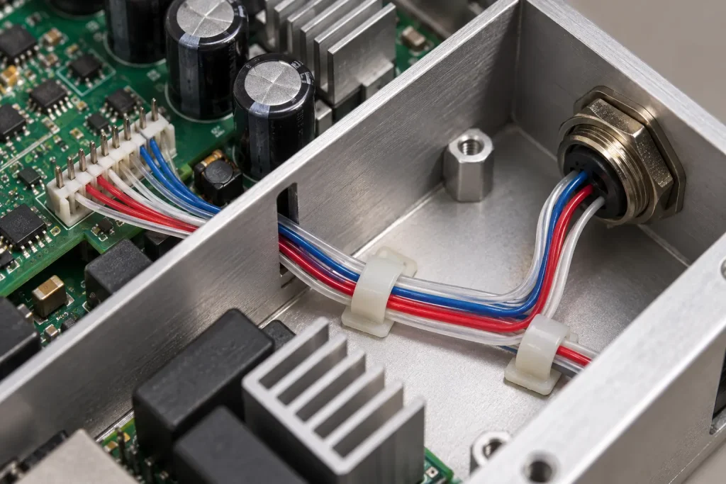
The verified insulation material is extruded PFA. It is not FEP, PTFE or ETFE, and “fluoroplastic” on its own does not define it — those are different materials or a higher-level category, and substituting any of them when specifying this Style changes what is being ordered.
“Fluoropolymer wire” works as a category term in commercial context. In a technical section or a BOM line, PFA is the specific material. No chemical-resistance percentage or chemical compatibility list is published here; where a specific fluid or process chemical is involved, that compatibility has to be established separately for the actual construction.
250°C Applies to the Wire
250°C is the verified Style rating — not an estimate, and not a marketing “up to” figure. It applies to the wire.
It does not follow that the complete electrical assembly, the connectors or the terminals are rated 250°C. In a dense assembly the wire is often not the limiting component, and the ratings of the hardware around it are separate questions belonging to the equipment design.
600 Vac Is an AC Rating
The verified rating is 600 Vac and is written that way in technical content rather than as an ambiguous “600V.” It is not restated as 600 Vdc, a 600V peak value, a dielectric withstand voltage, a surge voltage or an impulse rating unless separately documented.
Horizontal Flame Only
The verified rating includes Horizontal Flame. VW-1, FT1 and FT2 are separate flame classifications and are not claimed here, and Horizontal Flame is not converted into any of them.
Where a project specification calls for VW-1 or another classification, that is a separate requirement to be confirmed for the ordered construction rather than something the Style rating supplies.
Single Conductor
Style 10362 is defined as a single conductor with extruded insulation. This page concerns that insulated single conductor.
It is not a multi-core cable, a multi-conductor cable, a jacketed cable or a shielded cable. Where an assembly of that kind is required, it is a different product to specify.
Conductor Material and Plating Are RFQ Fields
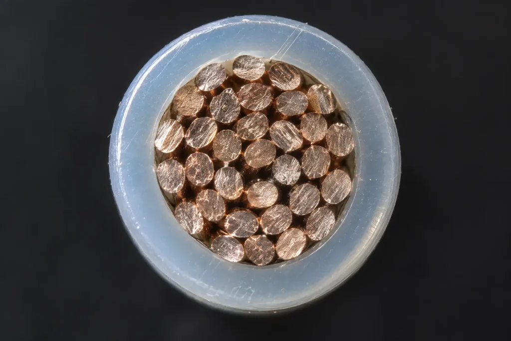
The Style information establishes 30 AWG–4/0 AWG, solid or stranded. It does not establish one universal conductor material or plating, so bare copper, tinned copper, silver-plated copper, nickel-plated copper and nickel conductor are none of them assumed on this page.
Strand count and strand diameter are likewise not established at Style level and are not invented here. Where the customer specification controls conductor material, plating or strand construction, state it in the enquiry so it can be confirmed against a qualified construction.
Solid or Stranded Must Be Specified
Both forms are permitted across the Style conductor range, so stranded is not a default. State which the construction requires, along with any strand construction the drawing controls.
Current Rating Is Not Published Here
The Style information supplied for this page does not provide an ampacity table, and none is published. No current rating by AWG, watts by AWG, recommended current load, power capacity or temperature derating table appears here.
Current requirement and conductor-size selection are buyer engineering inputs.
Selecting Conductor Size
AWG is not recommended here on the basis of equipment type. There is no basis in the Style data for saying that one size suits compact controls, another suits sensors, or another suits power sections — those are engineering decisions made against the actual load, temperature and dimensional requirements.
Send the required conductor size with the enquiry. Once the size is fixed, the applicable insulation band follows from it automatically.
Processing and Termination
No processing claim is made for PFA on this page — not easy stripping, clean stripping, easy crimping, better soldering or easy termination. Processing behaviour depends on the actual construction and on the equipment used, and is confirmed rather than assumed.
Where processed leads are required, supply the strip length, terminal part number, connector part number, crimp specification, finished lead length and drawing as applicable.
Compact Routing Requirements
For a space-constrained assembly, the information that makes an enquiry quotable is dimensional and mechanical:
- Available routing envelope
- Maximum finished OD
- Bend path, where mechanically controlled
- Connector-entry dimensions and terminal-block spacing
- Wire length
- Temperature and voltage requirement
- Conductor AWG
No minimum bend radius is published, because the Style data supplied here does not provide one. Where a bend path is mechanically controlled, describe the actual geometry rather than asking for a radius figure the Style cannot supply.
Official Use Boundary
The official Use for Style 10362 is: Internal wiring.
That is the complete wording, and it is deliberately narrow. Style 10362 is not building wire, field wiring, branch-circuit wiring, tray cable, conduit wiring, portable cord or external equipment power cable. Compact electrical assemblies sit inside internal equipment wiring as a buyer context; they do not extend the Use.
What UL 10362 Does Not Automatically Define
- Conductor material and conductor plating
- Strand count, strand diameter and conductor resistance
- Ampacity
- Finished OD and OD tolerance
- Minimum bend radius and flex-cycle life
- Chemical compatibility with a specific fluid
- Terminal and connector compatibility
- Cut length, reel length, MOQ, stock status and lead time
Common RFQ Mismatches
- Style 10362 requested with no AWG. Three insulation bands sit inside 30 AWG–4/0.
- 10 mil PFA assumed for every size. It applies to 30–10 AWG only.
- Change from 10 AWG to 9 AWG made without noticing the band change. The requirement triples to 30 mil average.
- Insulation wall treated as determining finished OD. It does not; OD comes from the construction.
- “Compact wire” requested with no maximum OD. Nothing can be checked against it.
- Tinned copper assumed. The Style fixes size and form, not conductor material.
- “600V” written without distinguishing the verified 600 Vac rating.
- Horizontal Flame read as VW-1 or FT1. Separate classifications requiring separate confirmation.
- Solid / stranded requirement omitted. Both are permitted.
- Minimum bend radius requested from the Style. The Style data does not provide one.
Each of these leaves the enquiry matching more than one qualified construction, and in a compact assembly the mismatch usually appears as a wire that meets every stated requirement and still will not fit the space it was ordered for.
RFQ Checklist
- UL AWM Style 10362
- Conductor AWG; 30–10 AWG construction band where applicable
- Solid or stranded
- Conductor material / plating, if controlled
- 250°C requirement
- 600 Vac requirement
- PFA insulation
- Nominal finished OD, if controlled
- Maximum finished OD and OD tolerance
- Routing-space limitation
- Terminal / connector details
- Strip length, if processed
- Finished lead length or reel requirement
- Quantity, packaging and destination
- Documentation requirements
- Actual compact internal electrical assembly context
Applicable RoHS / REACH documentation can be confirmed according to the ordered construction. UL marking is applied according to the confirmed ordered construction, and material is supplied as UL-recognized component wire under qualified manufacturing scope.