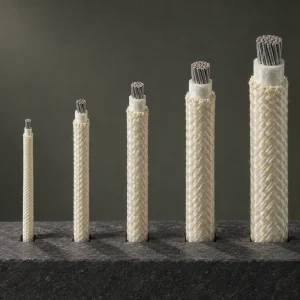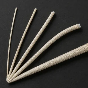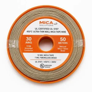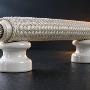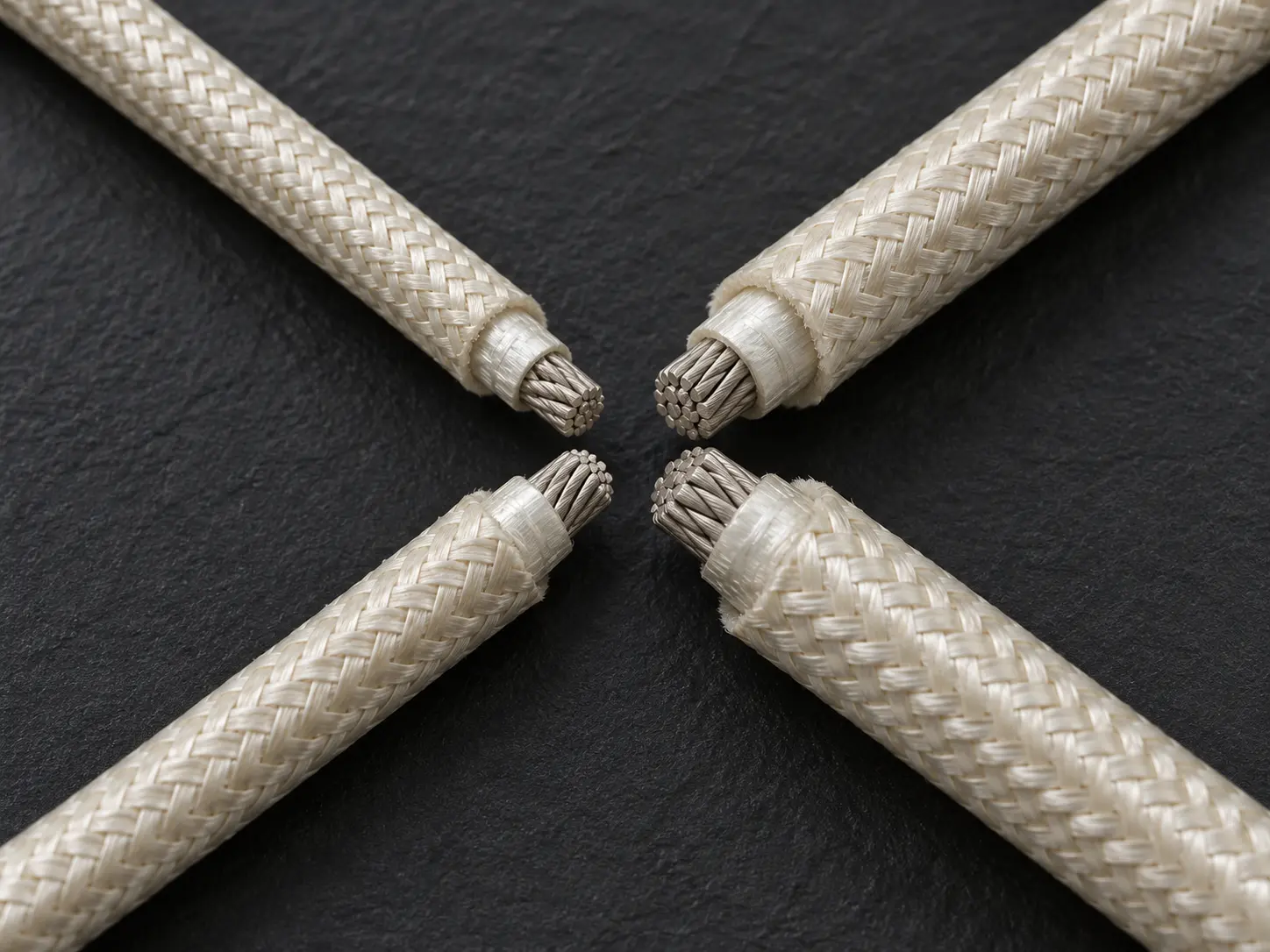
UL 5360 7–4 AWG Mica Wire for Protected Internal Wiring
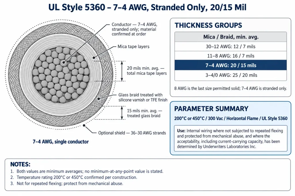
UL AWM Style 5360 is a single conductor with other-than-extruded insulation, rated 200 or 450°C and 300 Vac with a Horizontal flame classification. Its insulation is nonextruded mica tape with a glass braid treated with silicone varnish or TFE finish, and its thickness requirements are set by conductor-size group. For 7 AWG through 4 AWG, the Style requires a minimum average of 20 mils for the total mica tape layers and 15 mils for the treated glass braid, and every size in that group is stranded only. The Use is internal wiring where not subjected to repeated flexing and protected from mechanical abuse.
This page covers that 7–4 AWG single-conductor construction. The heavier 3 AWG–4/0 AWG group is covered on the UL 5360 3–4/0 AWG mica wire page, cabled assemblies on the UL 5360 Multi-Core Mica Glass Braid Cable page, and the broader Style overview in the UL 5360 Mica Wire category.
Verified UL 5360 Technical Specifications
| Parameter | UL AWM Style 5360 record |
|---|---|
| Style | 5360 |
| Description | Single conductor with other-than-extruded insulation |
| Temperature | 200 or 450°C |
| Voltage | 300 Vac |
| Flame | Horizontal flame |
| Overall conductor range | 30 AWG – 4/0 AWG |
| Conductor-form rule | Solid or stranded in sizes 26 – 8 AWG; larger sizes stranded only |
| This page’s range | 7 AWG – 4 AWG, stranded only |
| Insulation | Nonextruded Mica tape with Glass Braid |
| Thickness, 7 – 4 AWG | Total mica tape layers 20 mils (0.51 mm) min avg; treated glass braid 15 mils (0.38 mm) min avg |
| Braid treatment | Silicone Varnish or TFE Finish |
| Optional shield | 36 – 30 AWG Type “A” Nickel or 27 percent minimum nickel coated copper |
| Assembly provision | Single conductor, or two or more conductors cabled together, max O.D. 1.500 inches; mica glass binder and/or fiberglass fillers; optional overall treated glass braid |
| Marking | General |
| Use | Internal wiring where not subjected to repeated flexing and protected from mechanical abuse, and where the acceptability, including current-carrying capacity, has been determined by Underwriters Laboratories Inc. |
Four points in this table need clarification. First, the millimetre values are arithmetic conversions (1 mil = 0.0254 mm), not separate UL specifications. Second, both thickness values are minimum averages; the record states no minimum-at-any-point value. Third, the shield materials are for the optional shield only; the record does not state the primary conductor material or plating. Fourth, the temperature rating is 200 or 450°C; a given construction is qualified at one of them.
7–4 AWG Stranded-Conductor Construction
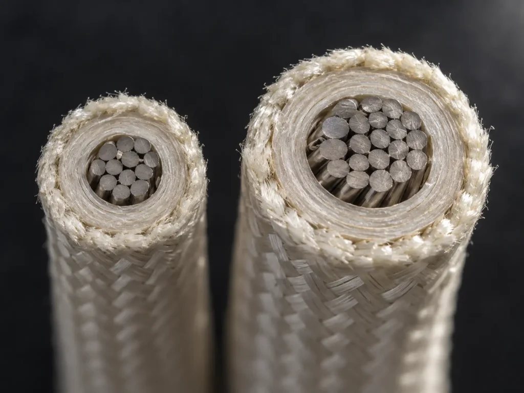
The conductor field reads: “30 AWG – 4/0 AWG. Solid or stranded in Sizes 26-8 AWG; larger sizes stranded only.” 7 AWG, 6 AWG, 5 AWG and 4 AWG are all larger than 8 AWG, so every size covered by this page must be stranded. A solid conductor is not a permitted Style 5360 construction in this group.
The group boundary and the conductor-form boundary meet at the same point. The preceding thickness group, 11–8 AWG, ends at 8 AWG, which is the largest size where a solid conductor is still permitted; the 7–4 AWG group begins at the first stranded-only size.
The record does not define strand count, strand diameter, conductor class, lay length, rope construction or flexibility class, and it does not specify conductor material, plating or resistance. These are confirmed according to the qualified ordered construction. The stranded form is a Style requirement here, not a flexibility feature, and the Use still excludes repeated flexing.
20 Mil Minimum-Average Mica Tape Layers
The Style’s thickness table is headed “Min Avg. thickness of total Mica tape layers.” For 7–4 AWG the value is 20 mils (0.51 mm by unit conversion).
- “Total mica tape layers”: the requirement applies to the combined thickness of all mica tape layers, not to a single tape.
- “Minimum average”: the average thickness of those combined layers must not fall below 20 mils.
The 20-mil figure is not nominal, exact or a minimum at any point. The actual mica thickness of an ordered construction may exceed it, and no tolerance is attached. The record does not specify the number of tape layers, tape width or overlap. The insulation is non-extruded mica tape; it is not described as composite mica glass, MI cable, mineral-insulated cable, silicone wire or ceramic cable.
15 Mil Minimum-Average Treated Glass Braid
Over the mica tape is a glass braid. For 7–4 AWG, the Style requires a minimum average braid thickness of 15 mils (0.38 mm by unit conversion). It is a minimum average only; it is not nominal or exact, and no point minimum is stated.
The braid column is headed “Glass braid treated with Silicone Varnish or TFE Finish.” Both treatments are permitted. The record does not assign silicone varnish to 200°C or TFE finish to 450°C, and this page does not make that link; the treatment and temperature rating for an order are confirmed for the qualified construction. The record makes no statement about relative abrasion, chemical, dielectric, flexibility or service-life behaviour of the treatments.
The mica and braid values are separate requirements and are not added together into a guaranteed finished diameter. The record does not imply any compactness, finished OD, dielectric strength, abrasion performance or bend radius from them. Where a drawing controls finished diameter or tolerance, it is confirmed against the ordered construction.
UL 5360 Thickness Schedule Across the Full Style Range
| AWG size | Total mica tape layers, min average | Treated glass braid, min average | Conductor form |
|---|---|---|---|
| 30 – 12 | 12 mils | 7 mils | Solid or stranded for 26 – 12 AWG |
| 11 – 8 | 16 mils | 7 mils | Solid or stranded |
| 7 – 4 (this page) | 20 mils | 15 mils | Stranded only |
| 3 – 4/0 | 25 mils | 20 mils | Stranded only |
Three points in this table need clarification. First, each group’s values apply only to that group: 8 AWG uses 16/7, 7 AWG uses 20/15, 4 AWG uses 20/15 and 3 AWG uses 25/20. Second, the record does not state the conductor form for 30–27 AWG, so the first row shows the rule only for 26–12 AWG. Third, all values are minimum averages, and the record attributes no performance difference to the larger values. The 7–4 AWG group, with its 20/15 mil requirement, remains the subject of this page.
200°C or 450°C, 300 Vac and Horizontal Flame
The rating field reads “200 or 450 deg C, 300 Vac, Horizontal flame.” The Style carries two alternative temperature ratings, so not every UL 5360 construction is a 450°C construction; the applicable rating is confirmed for the qualified ordered construction and its marking. Neither rating is described in the record as continuous or long-term. Because of this rating, UL 5360 can be described as high-temperature mica wire for protected internal wiring, without adding equipment approvals.
300 Vac is the voltage rating; no DC value or higher voltage applies, and the rating does not make the wire a power-distribution conductor. Horizontal flame is the flame classification; VW-1, FT1, FT2 and vertical flame are not Style-wide properties.
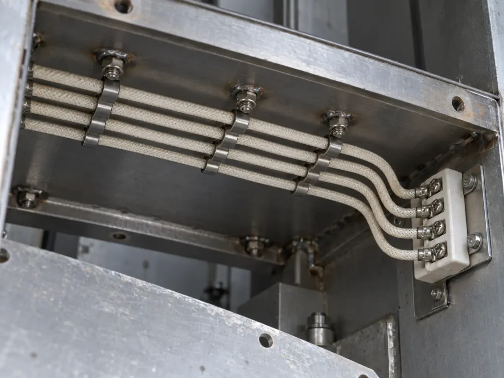
Protected Internal Wiring — No Repeated Flexing
The Use reads: “Internal wiring where not subjected to repeated flexing and protected from mechanical abuse, and where the acceptability, including current-carrying capacity, has been determined by Underwriters Laboratories Inc.” For 7–4 AWG single conductors:
- Internal wiring: the Use does not name industries or equipment, and none is designated here. Style 5360 is not described as essential to any particular industry.
- Not subjected to repeated flexing: the wire is not flexible, high-flex, continuous-flex, drag-chain or robotic cable, and no flex-life value is given.
- Protected from mechanical abuse: exposed routing, building, field, tray, outdoor, direct-burial and mechanically exposed machine routing fall outside the Use. The glass braid and the optional shield do not remove this condition.
- Acceptability, including current-carrying capacity, determined by UL: no current rating is assigned to 7, 6, 5 or 4 AWG, and this group is not described as high-current, high-power, heater-feed, bus or power-feed wire.
Optional Shield and Assembly Provisions
The Shield entry reads: “Optional. 36-30 AWG Type “A” Nickel or 27 percent minimum nickel coated copper.” These are shield materials, not the primary conductor material. The record establishes no EMI attenuation, shielding effectiveness, abrasion, mechanical or thermal-shielding performance for the shield.
The assembly entry permits a single conductor or two or more conductors “described above” to be cabled together, with a maximum O.D. of 1.500 inches, a mica glass binder and/or fiberglass fillers, and an optional overall treated glass braid. This page covers the single-conductor form; enquiries for a cabled assembly are handled on the UL 5360 Multi-Core Mica Glass Braid Cable page. No conductor counts are given here.
What Style 5360 Does and Does Not Define
For 7–4 AWG, the Style record defines the rating (200 or 450°C, 300 Vac, Horizontal flame); the stranded-only conductor form; the insulation (nonextruded mica tape with glass braid); the 20-mil minimum-average total mica tape layers; the 15-mil minimum-average treated glass braid; the braid treatments; the optional shield; the assembly provision; the marking field (General); and the Use.
The Style record does not define:
- conductor material, plating or strand construction
- conductor resistance or current rating
- minimum-at-any-point thicknesses
- finished outside diameter or tolerance
- which braid treatment applies to which temperature rating
- shielding performance
- bend radius, flex life or service life
Common Procurement Errors
- Specifying a solid conductor at 7–4 AWG.
- Applying the 16/7 mil values of 11–8 AWG to 7 AWG, or the 25/20 values of 3 AWG to 4 AWG.
- Treating 20 or 15 mils as nominal or point minimums.
- Assuming silicone varnish means 200°C and TFE finish means 450°C.
- Assuming every UL 5360 construction is rated 450°C.
- Reading a shield material as the conductor material.
- Assigning a current rating from AWG.
- Specifying the wire for repeated flexing or unprotected routing.
How to Specify UL 5360 7–4 AWG Mica Wire in an RFQ
The Style fixes the rating options, the stranded-only form at these sizes, the 20/15 mil minimum averages, the braid treatments, the shield option and the Use. The following should be stated by the buyer and confirmed for the ordered qualified construction, not filled with assumed values:
- exact AWG: 7, 6, 5 or 4 AWG
- required temperature rating: 200°C or 450°C
- conductor material and plating requirement
- detailed stranded construction, if controlled
- finished OD or tolerance, if controlled
- Silicone Varnish or TFE Finish requirement, if controlled
- optional shield requirement
- marking requirement
- equipment type
- internal routing condition
- confirmation that repeated flexing does not occur
- mechanical-protection arrangement
- current requirement
- quantity
- packaging requirement
- documentation requirement
UL Marking and Documentation
Style 5360 wire is supplied as UL-recognized component wire where supplied under qualified manufacturing scope. The marking field of the Style record reads “General”; it does not prescribe a fixed legend. UL marking is applied according to the confirmed ordered construction, including its temperature rating, and should be confirmed at the order stage.
Applicable RoHS / REACH documentation can be confirmed according to the ordered construction. CE, UKCA, CSA, FT1, VW-1, CPR, VDE, DIN, EN and IEC are not declared for this product.
Commercial, origin, compliance and transport documents are identified during quotation and confirmed according to the order.