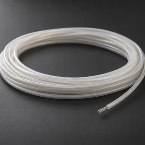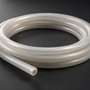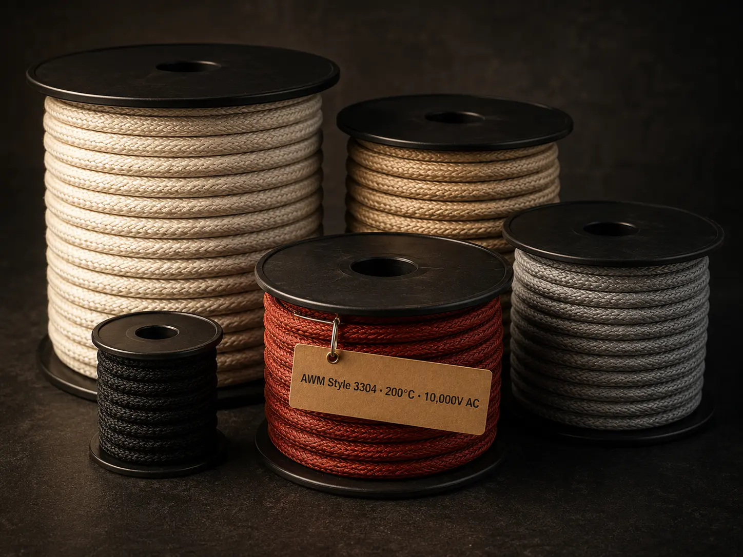
This page covers UL AWM Style 3573 supplied for burner system ignition circuits — the high-voltage lead between the ignition source and the electrode inside gas burner and fuel oil burner assemblies. Burner ignition procurement differs from range and cooktop procurement in the specification detail that typically comes with it: burner assemblies are usually built to a fixed lead length and a defined finished outside diameter that must clear the grommets and routing supports designed into the burner housing, so the order specification tends to be tighter than a general appliance internal lead.
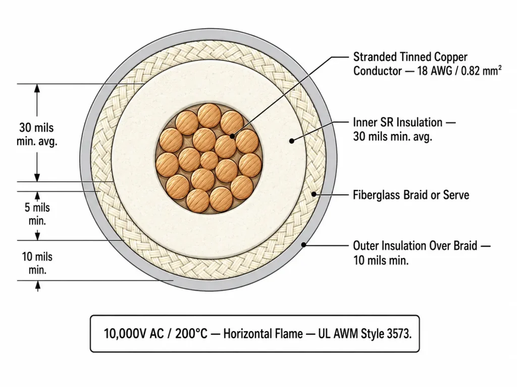
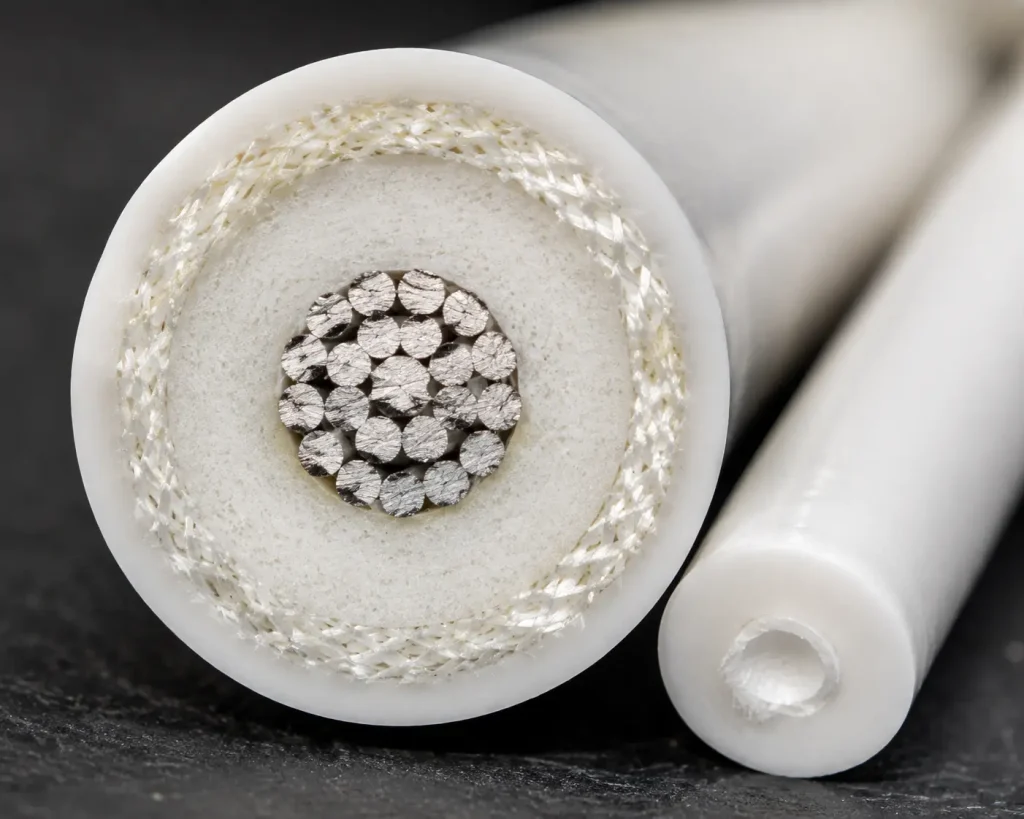
UL Style 3573 is an insulated wire rated 200°C and 10,000 Vac, covering 22 AWG through 12 AWG in solid or stranded round construction. The build is three-part: extruded SR silicone inner insulation, a fiberglass braid or serve over it, and extruded SR silicone outer insulation applied over the braid.
UL 3573 Ratings and Construction
| UL AWM Style | 3573 |
| Product description per Style file | Insulated wire |
| UL Subject / Section | 758, Section 3 |
| Temperature rating | 200°C |
| Voltage rating | 10,000 Vac |
| Conductor range | 22 AWG – 12 AWG, solid or stranded round |
| Inner insulation | Extruded SR silicone — 30 mils minimum average / 27 mils minimum at any point |
| Intermediate layer | Fiberglass braid or serve |
| Outer insulation | Extruded SR silicone over the braid — 10 mils minimum at any point |
| Flame rating | Horizontal flame per the UL Style file; VW-1 vertical flame testing available by confirmed construction and agreed order requirement |
| Marking | General, per UL Subject 758 marking requirements |
| Use per UL Style file | Electronic ignition or similar application in gas ranges or gas or fuel oil burner systems where protected from damage during handling, installation and servicing of the appliance |
22–12 AWG Order Options
The UL Style range is 22 AWG through 12 AWG in solid or stranded round construction. The Style file fixes the three insulation thicknesses but does not define a conductor material, plating, strand count, metric cross-section, finished outside diameter or conductor resistance. All of those are established at order stage. For burner assembly procurement, the finished outside diameter is often the value that needs settling first, since it determines whether the lead passes through the grommets and supports already designed into the housing.
| Order parameter | Confirmation status |
|---|---|
| AWG size | Within the UL Style range of 22–12 AWG; specify at enquiry |
| Solid or stranded round | Both within the UL Style scope; specify at enquiry |
| Conductor material | Not defined at Style level; requested material confirmed by quotation |
| Plating | Not defined at Style level; requested plating confirmed by quotation |
| Detailed stranding | Confirmed for the ordered construction |
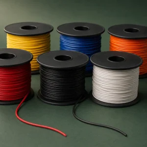
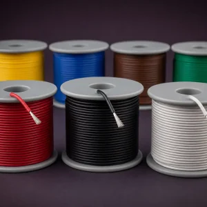
| Colour | Specify at enquiry; confirmed against production capability |
| Required finished outside diameter | Specify any dimensional constraint from the burner housing; confirmed for the ordered construction |
| Reel length | Specify at enquiry |
| Quantity | Specify at enquiry |
| Marking | Confirmed within the applicable certified scope before production |
| Packaging | Specify at enquiry; confirmed in the quotation |
| Required documents | Specify at enquiry; availability confirmed for the ordered construction |
Gas and Fuel Oil Burner Ignition Applications
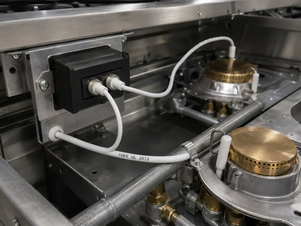
The UL Style file states the use as electronic ignition or similar application in gas ranges or gas or fuel oil burner systems, where protected from damage during handling, installation and servicing of the appliance. Within that scope, this page covers the two burner-system cases:
- Gas burner systems — the ignition lead routed within the burner assembly housing between the ignition source and the electrode position.
- Fuel oil burner systems — the lead from the ignition transformer to the spark electrodes, routed within the burner enclosure.
Both are protected internal routing cases: the lead runs inside the burner housing along a defined path with the enclosure providing protection. Suitability for a specific burner design is not established by the Style rating alone — it depends on the equipment, the routing arrangement, the ordered construction and the applicable equipment-level evaluation.
Protected Routing and Equipment Conditions
The protection requirement in the Style file names three phases: handling, installation and servicing. For burner systems, all three carry practical weight.
During handling, the lead is often supplied cut to length and moved through an assembly line before it reaches the burner. During installation, it is threaded through the housing and connected at both ends. During servicing, burner assemblies are frequently opened for electrode cleaning or replacement, and the ignition lead is one of the components most likely to be disturbed in that process. A routing arrangement that protects the lead in the assembled burner but exposes it whenever the housing is opened for service does not satisfy the condition.
This Style is not for open routing, direct combustion exposure or any installation outside the protected internal path within the equipment. Confirm the routing and service access arrangement against the protection requirement before specifying a construction.
UL 3573 and UL 3304 Construction Difference
Both Styles are rated 200°C and 10,000 Vac across 22–12 AWG, and both are stated for electronic ignition applications in gas ranges and gas or fuel oil burner systems. The difference is structural.
UL 3573 has extruded SR silicone inner insulation at 30 mils minimum average, a fiberglass braid or serve over it, and extruded SR silicone outer insulation over the braid at 10 mils minimum at any point. UL 3304 has extruded SR silicone insulation at 40 mils minimum average with a fiberglass braid covering, and no silicone outer insulation listed over the braid.
The two therefore differ in the thickness of the silicone under the braid and in whether the braid is the outermost layer. Which construction a burner design specifies is determined by that design, not by a general ranking between the Styles.
UL Marking and Order Documentation
The ordered construction, the applicable certified scope, the actual UL marking applied and the supporting documents must all be confirmed before production. Only products bearing the applicable UL Mark should be represented as covered products.
Where UL, RoHS, REACH or other compliance documents are required, specify them during enquiry so their availability can be confirmed for the ordered construction. Minimum order quantity, sample availability, packaging, delivery schedule and marking are confirmed in the quotation.
Related UL 3573 Ignition Wire Products
For the full range of UL 3573 constructions, see the UL 3573 ignition wire category. For a broader treatment covering protected ignition circuits across gas ranges as well as burner systems, see UL 3573 ignition wire for protected ignition circuits. The wider ranges are available under High Voltage Wire and AWM Wire.
Request a Burner Ignition Wire Quote
Send the following with your enquiry so the construction can be confirmed against the applicable certified scope:
- AWG size within the 22–12 AWG Style range
- Solid or stranded round requirement
- Requested conductor material and plating
- Colour
- Required finished outside diameter, including any constraint from the burner housing
- Reel length
- Quantity
- Packaging format
- Actual burner or ignition equipment type
- Ignition-system voltage requirement
- Routing and protection conditions, including service access arrangements
- Required wire marking
- Required order documents